26. Debounce and Signal Conditioning in PLC Logic (26 of 41)

In industrial automation, not every input signal is clean.
A sensor may flicker.
A push button may bounce.
A limit switch may chatter.
A photoeye may blink because of vibration, dust, or product movement.
A pressure switch may rapidly change state near its setpoint.
To the PLC, these small unstable changes may look like real ON/OFF events.
That can create problems like:
False counts
False machine starts
Unstable sequences
Random faults
Bad reject timing
Incorrect product detection
Repeated alarms
Timer resets
Counter overcounting
This is why PLC programs often use debounce and signal conditioning.
A simple way to say it:
Debounce cleans up unstable input signals before the PLC logic uses them.
1. What Is Debounce?
Debounce is a logic method used to confirm that an input has stayed ON or OFF long enough before the program accepts it as valid.
Simple definition:
Debounce = Filtering short, unwanted input changes before using the signal in logic.Example:
Raw sensor flickers ON for 20 ms
Debounce timer requires 100 ms
PLC ignores the flicker
The goal is to separate real signals from noise.
2. Why Inputs Bounce or Flicker
Inputs may bounce or flicker for many reasons.
Common causes:
Mechanical contact bounce
Vibration
Loose sensor bracket
Dirty photoeye lens
Electrical noise
Bad cable shield
Loose terminal
Weak 24 VDC power
Product movement
Reflective surfaces
Pressure switch near setpoint
Limit switch actuator vibration
Relay contact chatter
Some of these are electrical problems.
Some are mechanical problems.
Some are application problems.
Important:
Debounce can help stabilize a signal, but it should not be used to hide a real mechanical or wiring problem.
3. Raw Input vs Valid Input
A professional PLC program often separates the raw input from the conditioned input.
Example:
Raw_Input = physical PLC input
Valid_Input = cleaned signal used by logic
For example:
Local:1:I.Data.0       = Raw photoeye input
DI_BoxPresent_Raw      = buffered raw input
DI_BoxPresent_Valid    = debounced valid input
The machine logic should normally use:
DI_BoxPresent_Validnot the unstable raw input directly.
4. Basic Debounce Concept
A debounce usually works like this:
Raw Input turns ON
        ↓
ON-delay timer starts
        ↓
If raw input stays ON long enough
        ↓
Valid Input turns ON
And for OFF debounce:
Raw Input turns OFF
        ↓
OFF-delay timer starts
        ↓
If raw input stays OFF long enough
        ↓
Valid Input turns OFF
This prevents quick flickers from changing the valid signal.
5. ON Debounce
ON debounce confirms that a signal is truly ON.
Example:
Raw photoeye must be ON for 100 ms
before BoxPresent_Valid turns ON.
This is useful when a signal briefly turns ON because of noise or product vibration.
Logic concept:
Raw_Input ON for debounce time
= Valid_Input ON
Common uses:
Photoeye product detection
Push button confirmation
Proximity sensor confirmation
Limit switch confirmation
Pressure switch confirmation
6. OFF Debounce
OFF debounce confirms that a signal is truly OFF.
Example:
Raw photoeye must be OFF for 100 ms
before BoxPresent_Valid turns OFF.
This is useful when the sensor briefly drops out because of vibration, dust, glare, or target movement.
Logic concept:
Raw_Input OFF for debounce time
= Valid_Input OFF
OFF debounce is very useful when you do not want a small dropout to reset a sequence or timer.
7. Why Use Both ON and OFF Debounce?
Some signals need debounce in both directions.
Example:
Photoeye turns ON because box arrives.
Photoeye turns OFF because box leaves.
If both transitions matter, you may need:
ON debounce  = confirm object present
OFF debounce = confirm object gone
This creates a stable valid signal.
Example:
Raw_Photoeye → Debounce Logic → Valid_PhotoeyeThen the rest of the program uses the valid bit.
8. Debounce Using TON Timers
A common PLC method uses TON timers.
ON debounce
Raw_Input ON → TON On_Delay
On_Delay.DN → turn ON Valid_Input
OFF debounce
Raw_Input OFF → TON Off_Delay
Off_Delay.DN → turn OFF Valid_Input
This is simple and works well in RSLogix 500 and Studio 5000.
9. Example: Photoeye Debounce
Problem:
Photoeye flickers when boxes pass on a vibrating conveyor.Without debounce:
PLC sees several ON/OFF transitions.
Counter may count too many times.
Sequence may reset.
Jam timer may behave incorrectly.
With debounce:
Photoeye must stay ON for 100 ms before accepted.
Photoeye must stay OFF for 100 ms before cleared.
Result:
Cleaner product detection
More stable counting
Fewer false triggers
Better sequence control
10. Example: Push Button Debounce
Mechanical push buttons can bounce internally when pressed.
The PLC may see:
ON-OFF-ON-OFF-ONvery quickly.
A debounce timer can convert that into one stable press.
Example:
Start_PB_Raw ON for 50 ms
= Start_PB_Valid ON
For commands like Start or Reset, you may also use a one-shot after debounce.
Example:
Start_PB_Raw
    ↓
Debounce
    ↓
Start_PB_Valid
    ↓
One-Shot
    ↓
Start_Request
This gives one clean request per press.
11. Example: Pressure Switch Chatter
A pressure switch may chatter when pressure is near its setpoint.
Example:
Pressure switch setpoint = 60 PSI
Process pressure fluctuates between 59.8 and 60.2 PSI
The switch may rapidly turn ON and OFF.
Debounce can help, but the better solution may also include:
Hysteresis
Correct switch setpoint
Better pressure regulation
Analog pressure transmitter
Mechanical inspection
Process tuning
Important:
If a switch chatters because the process is unstable, debounce alone may not solve the real problem.
12. Debounce vs One-Shot
Debounce and one-shot are not the same.
Debounce
Debounce cleans and stabilizes the input.
Raw noisy signal → Stable valid signalOne-Shot
A one-shot creates a one-scan pulse when a clean signal transitions.
Stable signal turns ON → One-scan pulseUse them together when needed.
Example:
Photoeye_Raw
    ↓
Debounce
    ↓
Photoeye_Valid
    ↓
One-Shot
    ↓
Counter
This is a strong pattern for product counting.
13. Debounce vs Filtering
The words debounce and filtering are sometimes used together.
Debounce
Usually used for discrete ON/OFF signals.
Examples:
Push buttons
Photoeyes
Limit switches
Proximity sensors
Pressure switches
Filtering
Often used for analog values or noisy signals.
Examples:
Pressure_PSI
Tank_Level_Pct
Flow_GPM
Weight_lbs
Temperature_F
Analog filtering may use:
Moving average
Low-pass filter
Module filter setting
HMI smoothing
PLC calculation
Do not confuse discrete debounce with analog filtering.
14. Choosing a Debounce Time
The debounce time should be long enough to reject false transitions, but short enough to not slow down the machine.
Typical starting values:
Push button: 30–100 ms
Limit switch: 50–150 ms
Photoeye: 20–100 ms
Noisy mechanical contact: 100–300 ms
Slow process switch: 500 ms or more, depending on process
But the correct value depends on the machine.
Too short:
Noise still passes through.Too long:
Machine response becomes delayed.
Fast products may be missed.
Sequence timing may be affected.
15. Debounce and High-Speed Inputs
Be careful with fast-moving products or high-speed counting.
If the object passes the sensor quickly, a long debounce may ignore the product.
Example:
Product blocks photoeye for 40 ms
Debounce time = 100 ms
Result: PLC never accepts product
For high-speed counting, use:
High-speed input modules
Encoder inputs
Proper sensor selection
Correct scan time considerations
Short debounce or hardware filtering
One-shot logic
Debounce must match the process speed.
16. Hardware Input Filters
Some PLC input modules have built-in input filters.
These may be configured in the hardware module settings.
Examples:
Input filter time
Off-to-On filter
On-to-Off filter
Digital input delay
Module filter configuration
Hardware filtering can be useful because it happens before the PLC logic uses the signal.
But software debounce is still useful when you want logic-specific filtering or better visibility.
Technician note:
Check the PLC input module configuration if an input responds slower than expected.The delay may be caused by hardware filter settings.
17. Signal Conditioning Beyond Debounce
Signal conditioning means preparing a signal so it is reliable and useful for logic.
For discrete inputs, this may include:
Input buffering
Debounce
One-shot generation
Inverting normally closed signals
Fault detection
Status bits
HMI diagnostic bits
For analog inputs, signal conditioning may include:
Scaling
Filtering
Fault detection
Clamp limits
Engineering units
Alarm thresholds
Rate-of-change monitoring
The goal is to give the rest of the PLC program a clean, meaningful signal.
18. Recommended Discrete Input Structure
A professional input structure may look like this:
1. Raw Input
2. Buffered Input
3. Debounced Input
4. Valid Input
5. One-Shot if needed
6. Diagnostic Status
Example:
Local:1:I.Data.4
    ↓
DI_PE1_Raw
    ↓
DI_PE1_Debounced
    ↓
DI_PE1_Valid
    ↓
ONS_PE1_Detected
This makes troubleshooting easier because each step is visible.
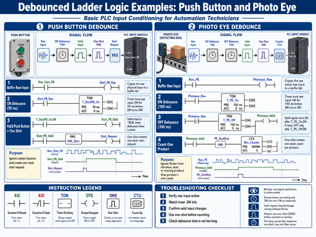
19. PLC Troubleshooting Example
Problem:
Box counter is counting extra boxes.Possible causes:
Photoeye flicker
Product vibration
Reflective surface
No one-shot
No debounce
Sensor bracket loose
Cable noise
PLC logic counting raw input directly
Troubleshooting path:
1. Watch raw photoeye input online.
2. Watch debounced valid input.
3. Watch one-shot pulse.
4. Watch counter ACC.
5. Check sensor alignment.
6. Check bracket vibration.
7. Check cable routing.
8. Adjust debounce time carefully.
9. Test with real product speed.
Root cause example:
Raw photoeye flickered several times as one box passed.
Counter used raw input without debounce or one-shot.
Correction:
Add debounce.
Add one-shot.
Use one-shot pulse to increment counter.
20. Common Mistakes
Mistake 1 — Using raw inputs directly everywhere
Raw signals may be unstable.
Mistake 2 — Adding too much debounce
A long debounce can miss fast events.
Mistake 3 — Using debounce to hide mechanical problems
If the sensor bracket is loose, fix the bracket.
Mistake 4 — Forgetting OFF debounce
A signal may be stable turning ON but unstable turning OFF.
Mistake 5 — Counting without one-shot
Debounce stabilizes the signal, but a counter may still need a one-shot.
Mistake 6 — Ignoring hardware input filters
The PLC module may already have input filtering configured.
21. Best Practices
Use these best practices:
Buffer raw inputs.
Debounce noisy discrete inputs.
Use separate ON and OFF debounce when needed.
Use one-shots for event counting.
Use unique one-shot storage bits.
Choose debounce time based on machine speed.
Check sensor mounting before changing logic.
Check wiring and shielding for noise.
Use hardware filters when appropriate.
Document debounce times.
Show important valid signals on HMI diagnostics.
Avoid using raw inputs directly in command logic.
22. Technician Checklist
When reviewing debounce logic, ask:
Is the raw input stable?
Is the sensor mechanically secure?
Is the cable protected and routed correctly?
Is electrical noise possible?
Is the input filtered in hardware?
Is software debounce needed?
Is ON debounce needed?
Is OFF debounce needed?
Is the debounce time reasonable?
Could the debounce time miss fast products?
Is the valid input used by logic?
Is a one-shot needed after debounce?
Is the counter using the one-shot pulse?
Are tags clearly named?
Is the debounce documented?
Final Thoughts
Debounce and signal conditioning are essential for reliable PLC logic.
A PLC is very fast.
That is good for control, but it also means the PLC may detect short unwanted transitions that humans cannot see.
That is why raw inputs should often be processed before they are used in machine logic.
A clean structure looks like this:
Raw Input → Buffer → Debounce → Valid Input → One-Shot → LogicThis improves:
Counting accuracy
Sequence reliability
Fault detection
Machine stability
Troubleshooting clarity
But remember:
Debounce should clean the signal, not hide the real problem.
If the cause is a loose bracket, damaged cable, bad sensor, poor grounding, or unstable process, fix the root cause.
A strong automation technician knows when to use debounce and when to investigate deeper.