9. Control Circuit vs Power Circuit
One of the most important concepts an automation technician must understand is the difference between the control circuit and the power circuit.
Many industrial machines use both.
The control circuit makes the decision.
The power circuit performs the work.
A PLC output may turn ON, but that does not mean the motor has power.
A contactor may pull in, but that does not mean the PLC logic is correct.
A fuse may be good in the control circuit, but a power fuse may still be blown.
A motor may not run because the control circuit is open, or because the power circuit is missing voltage.
That is why a technician must learn to separate the two.
1. The Simple Difference
Control Circuit
The control circuit is the low-power circuit used to control devices.
It includes the signals, commands, permissives, interlocks, PLC outputs, push buttons, relays, and coils that tell the machine what to do.
Simple definition:
Control Circuit = The circuit that controls the action.Power Circuit
The power circuit is the high-power circuit that supplies energy to the load.
It includes the conductors, breakers, fuses, contactor power contacts, overloads, VFD output, and motor leads that actually power the equipment.
Simple definition:
Power Circuit = The circuit that performs the work.2. Basic Example
A motor starter has both circuits.
Control Circuit:
Start PB → Stop PB → Overload NC Contact → Contactor Coil

Power Circuit:
L1/L2/L3 → Breaker/Fuses → Contactor Power Contacts → Overload → Motor
When the control circuit energizes the contactor coil, the contactor closes the power contacts.
Then the power circuit sends voltage to the motor.
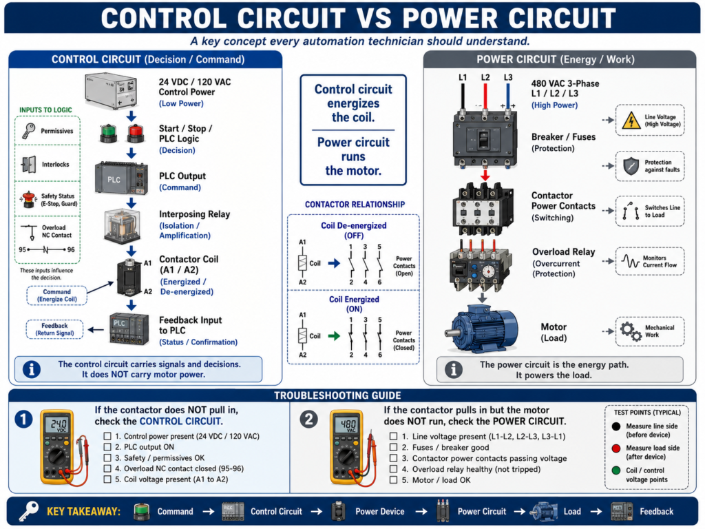
Control circuit energizes the coil.
Power circuit runs the motor.
3. Why This Matters in Troubleshooting
When a motor does not run, you need to know which side failed.
Possible control circuit problems:
Stop circuit open
E-stop active
Overload auxiliary contact open
PLC output OFF
Relay coil failed
Contactor coil failed
No 24 VDC control power
No 120 VAC control power
Broken control wire
Safety relay output open
Possible power circuit problems:
Main disconnect OFF
Breaker tripped
Power fuse blown
No line voltage
Bad contactor power contact
Overload power section issue
Loose motor lead
Bad motor cable
Motor winding problem
Mechanical jam causing overload
If you do not separate the circuits, you may troubleshoot in the wrong direction.
4. Common Control Circuit Voltages
Control circuits usually use lower voltage than power circuits.
Common examples:
24 VDC
120 VAC
110 VAC
230 VAC in some systems
In modern automation, 24 VDC is very common for:
PLC inputs
PLC outputs
Sensors
Relays
Solenoids
Interposing relays
Safety status signals
VFD digital inputs
Older machines may use 120 VAC control circuits for push buttons, relay coils, contactor coils, and pilot lights.
5. Common Power Circuit Voltages
Power circuits carry the energy for real loads.
Common examples:
120 VAC single-phase
240 VAC single-phase
240 VAC three-phase
480 VAC three-phase
575 VAC three-phase
Power circuits may feed:
Motors
Heaters
Pumps
Fans
Compressors
VFD input power
Large solenoid loads
Transformers
Power supplies
Power circuits are more dangerous because they usually carry higher voltage and higher current.
Always follow lockout/tagout procedures and verify absence of voltage before working.
6. PLCs Usually Control Indirectly
A PLC usually does not directly power large loads.
Instead, it controls another device that controls the load.
Example:
PLC Output
    ↓
Interposing Relay
    ↓
Contactor Coil
    ↓
Contactor Power Contacts
    ↓
Motor
The PLC output belongs to the control circuit.
The motor power belongs to the power circuit.
This separation protects the PLC and allows small control signals to operate large loads.
7. Relays as Interface Devices
Relays often sit between control circuits and power circuits.
They may be used for:
Isolation
Voltage conversion
Current amplification
PLC output protection
Switching different voltage levels
Interposing between PLC and field devices
Example:
24 VDC PLC output energizes a relay coil.
Relay contact switches 120 VAC to a contactor coil.
Contactor power contacts switch 480 VAC to the motor.
In that example, there are multiple levels:
24 VDC PLC control
120 VAC contactor coil control
480 VAC motor power
A technician must identify each voltage level clearly.
8. Contactor Coil vs Contactor Power Contacts
A contactor is a perfect example of control vs power.
Coil Side
The coil is part of the control circuit.
Typical terminals:
A1 and A2When the coil receives the correct control voltage, the contactor pulls in.
Power Contact Side
The main contacts are part of the power circuit.
Typical terminals:
L1, L2, L3 = incoming line power
T1, T2, T3 = output to motor
When the contactor pulls in, L1 connects to T1, L2 connects to T2, and L3 connects to T3.
Important:
A contactor can pull in but still have a bad power contact.So when troubleshooting, check both:
Is coil voltage present?
Are power contacts passing voltage?
9. Overload Relay: Control and Power Side
An overload relay also connects both worlds.
Power Side
Motor current passes through the overload relay.
The overload monitors current and protects the motor from excessive current over time.
Control Side
The overload usually has a normally closed auxiliary contact in the control circuit.
Common terminal numbers may be:
95-96 = Normally Closed overload contact
97-98 = Normally Open trip indication contact
When the overload trips:
Power side detects overload condition.
Control side opens the NC contact.
Contactor coil drops out.
Motor stops.
This is a great example of the power circuit affecting the control circuit.
10. VFD Control vs VFD Power
A VFD also has control and power sections.
VFD Power Circuit
Power circuit:
Incoming 3-phase AC power → VFD input terminals → VFD output terminals → MotorTypical power terminals:
L1 / L2 / L3 = input power
T1 / T2 / T3 or U / V / W = output to motor
VFD Control Circuit
Control circuit:
Start input
Stop input
Enable input
Speed reference
Fault reset input
Relay output
Communication network
Safe Torque Off
A VFD may have power and a display, but still not run if the control circuit is not correct.
Check:
Start command
Enable input
Stop input
Speed reference
Local/Remote mode
Network command
Safe Torque Off
Fault status
11. Control Circuit Troubleshooting Example
Problem
Motor does not start. The contactor does not pull in.
That points first toward the control circuit.
Check:
Is control voltage present?
Is the Stop PB closed?
Is the E-stop/safety circuit healthy?
Is the overload NC contact closed?
Is the PLC output ON?
Is the relay coil energizing?
Is voltage reaching contactor A1/A2?
Is the contactor coil good?
If the contactor coil never energizes, the power circuit may not be the first place to start.
The control circuit is not asking the motor to run.
12. Power Circuit Troubleshooting Example
Problem
Motor does not run, but the contactor pulls in.
That means the control circuit may be working.
Now check the power circuit.
Check:
Is line voltage present at L1/L2/L3?
Is voltage present at T1/T2/T3 when contactor pulls in?
Are power fuses good?
Is the breaker ON?
Is the overload power path good?
Are motor leads connected?
Is the motor cable damaged?
Is the motor mechanically jammed?
If the contactor pulls in but no voltage reaches the motor, the problem is likely in the power circuit.
13. PLC Output ON Does Not Prove Load ON
This is a common mistake.
A PLC output LED may be ON, but the field device may not energize.
Possible causes:
Output fuse blown
No field power
Bad output module
Broken wire
Bad relay coil
Relay not seated
Bad relay contact
Missing common/neutral
Bad solenoid coil
Mechanical valve issue
The PLC output is only one point in the control chain.
You still need to verify voltage at the load.
14. Motor Running Feedback
A professional system often uses feedback to prove that the power circuit responded.
Examples:
Contactor auxiliary contact
VFD running status
Motor current sensor
Encoder speed feedback
Flow switch after pump starts
Pressure increase after pump starts
This gives the PLC proof that the command caused real action.
Control command:
PLC asks motor to run.Feedback:
Motor starter or VFD confirms the motor responded.15. Safe Troubleshooting Mindset
Because power circuits can involve dangerous voltage and current, safety comes first.
Before working inside a panel:
Follow lockout/tagout.
Use proper PPE.
Verify the correct panel.
Check drawings.
Identify voltage levels.
Use the correct meter category.
Verify absence of voltage when required.
Never assume a circuit is dead.
Control circuits can also be dangerous, especially 120 VAC or higher control wiring.
Treat every circuit with respect.
16. Technician Method: Separate the Problem
When troubleshooting, ask:
Is the control circuit working?
Is the power circuit working?
Then break it down.
For the control circuit
Command present?
Permissives OK?
Interlocks clear?
Output ON?
Relay/coil energized?
Common/neutral return good?
For the power circuit
Line voltage present?
Protection devices healthy?
Power contacts closing?
Load voltage present?
Motor/load healthy?
Current normal?
This approach prevents guessing.
17. Example: Full Troubleshooting Path
Problem
Conveyor motor does not start.
Step 1 — Check command
Does the PLC/HMI command the conveyor to run?Step 2 — Check control circuit
Is PLC output ON?
Is relay energized?
Is contactor coil voltage present?
Does contactor pull in?
Step 3 — Check power circuit
Is 480 VAC present at L1/L2/L3?
Is 480 VAC present at T1/T2/T3 after contactor pulls in?
Is overload healthy?
Are motor leads connected?
Step 4 — Check feedback
Does auxiliary contact turn ON?
Does PLC see motor feedback?
Does motor current look normal?
Step 5 — Check mechanical load
Is conveyor jammed?
Is gearbox locked?
Is chain broken?
Is motor coupling damaged?
This is how a technician thinks through the complete system.
18. Common Mistakes
Mistake 1 — Checking only the PLC
The PLC may be commanding correctly, but the electrical circuit may have failed.
Mistake 2 — Checking only the power side
The motor may have power available, but the control circuit may not be energizing the starter.
Mistake 3 — Assuming a pulled-in contactor means the motor has voltage
A contactor can pull in and still have bad contacts, missing line voltage, or blown fuses.
Mistake 4 — Ignoring the return path
A coil or load needs a complete circuit, including common or neutral.
Mistake 5 — Not identifying voltage levels
A panel may have 24 VDC, 120 VAC, and 480 VAC in the same enclosure.
Mistake 6 — Resetting protection devices without finding the cause
A blown fuse, tripped breaker, or overload trip is a symptom.
19. Technician Checklist
When troubleshooting control vs power problems, verify:
Correct drawings available
Voltage levels identified
Control power present
Power circuit voltage present
Fuses and breakers healthy
Safety circuit healthy
PLC command present
PLC output ON
Relay/contactor coil voltage present
Contactor pulls in
Power contacts pass voltage
Overload healthy
Load receives voltage
Feedback returns to PLC
Current is normal
Mechanical load is free
Root cause documented
Final Thoughts
Understanding the difference between the control circuit and the power circuit is a major step for any automation technician.
The control circuit decides what should happen.
The power circuit makes it happen.
A motor does not run just because the PLC output is ON.
A solenoid does not energize just because the logic is true.
A VFD does not run just because it has power.
The full path must be healthy.
Command → Control Circuit → Power Device → Power Circuit → Load → FeedbackWhen troubleshooting, separate the problem.
Check the control side.
Check the power side.
Check the feedback.
Use the drawings.
Use the meter.
Find where the chain breaks.
Control tells the machine what to do. Power gives the machine the energy to do it.