8. Inside an Industrial Control Panel (8 of 41)
Inside an Industrial Control Panel
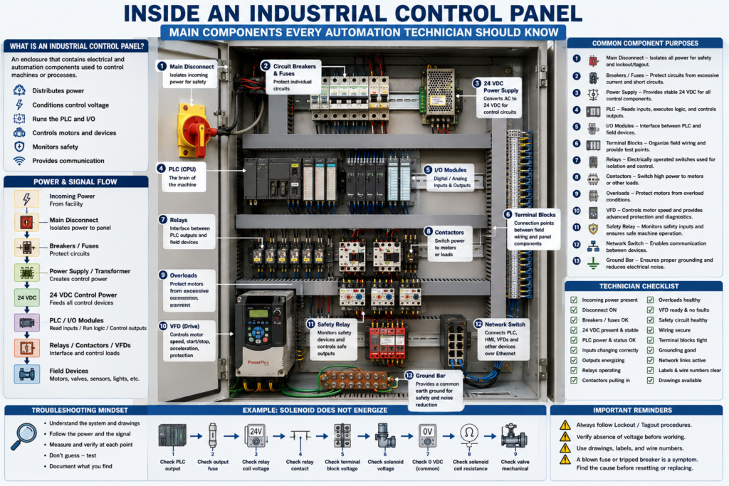
An industrial control panel is the heart of many automation systems.
Inside the panel, power is distributed, control voltage is created, PLCs make decisions, inputs and outputs are connected, motors are controlled, safety circuits are monitored, and communication networks are organized.
For an automation technician, learning how to understand a control panel is a major step toward becoming confident in the field.
A control panel may look complicated at first because it contains many devices, wires, terminal blocks, labels, and drawings.
But once you understand the purpose of each component, the panel becomes easier to read.
The goal is not to memorize every part immediately.
The goal is to understand how power, signals, commands, feedback, and communication move through the system.
1. What Is an Industrial Control Panel?
An industrial control panel is an enclosure that contains electrical and automation components used to control a machine or process.
A panel may control:
Conveyors
Pumps
Motors
Valves
Fillers
Mixers
Packaging machines
Robots
Process systems
Safety circuits
Remote I/O
Instrumentation
A simple way to think about it:
The control panel is where the machine’s electrical power, control logic, field wiring, and communication come together.Inside the panel, you may find:
Disconnect switch
Circuit breakers
Fuses
24 VDC power supplies
PLC
I/O modules
Relays
Contactors
Overloads
VFDs
Safety relays
Terminal blocks
Network switches
Ground bar
Wire duct
Labels and wire numbers
2. Main Disconnect
The main disconnect is used to isolate power going into the panel.
It is usually located on the panel door or connected to an external handle.
Its purpose is to disconnect incoming power so the panel or machine can be serviced safely.
Common functions:
Turns incoming power ON or OFF
Provides isolation
Allows lockout/tagout
Controls main power feeding the panel
Important:
Never assume a panel is safe just because the disconnect is OFF. Always follow plant lockout/tagout procedures and verify absence of voltage.
Some panels may still contain live power even when one disconnect is OFF, depending on the design.
3. Circuit Breakers and Fuses
Breakers and fuses protect electrical circuits from excessive current.
They protect wiring and equipment.
They are not just switches.
Circuit Breaker
A breaker can trip when current exceeds its rating.
It can usually be reset after the fault is corrected.
Common uses:
Main power protection
Branch circuit protection
Control transformer protection
Power supply protection
Motor circuit protection
Fuse
A fuse opens permanently when excessive current flows.
It must be replaced after it blows.
Common uses:
Control circuits
Power supplies
PLC output protection
Solenoid circuits
Sensor branches
Instrument loops
Important technician mindset:
A blown fuse or tripped breaker is a symptom.
Find the cause before resetting or replacing it.
Possible causes:
Short circuit
Ground fault
Failed device
Damaged cable
Incorrect wiring
Overloaded circuit
Wrong fuse size
4. Power Supply
A 24 VDC power supply converts AC voltage into DC control voltage.
Common input voltages:
120 VAC
240 VAC
480 VAC through transformer or panel design
Common output:
24 VDCThe 24 VDC power supply may feed:
PLC inputs
PLC outputs
Sensors
Relays
Solenoids
Remote I/O
Network switches
HMI circuits
Analog transmitters
Safety devices
When a machine has strange control problems, always verify the 24 VDC power supply.
Check:
AC input present
24 VDC output correct
Power supply not overloaded
Main and branch fuses good
0 VDC common connected
Voltage stable under load
5. PLC
The PLC is the controller.
It reads inputs, executes logic, and controls outputs.
A PLC system may include:
CPU
Power supply module
Digital input modules
Digital output modules
Analog input modules
Analog output modules
Communication modules
Remote I/O adapters
Basic PLC flow:
Inputs → PLC Logic → OutputsThe PLC receives signals from devices such as:
Push buttons
Sensors
Limit switches
Pressure switches
Safety status contacts
Motor feedback contacts
VFD status outputs
Then it controls devices such as:
Relays
Solenoids
Motor starters
VFD run commands
Lights
Buzzers
Valves
A technician should know where the PLC is located, how the I/O modules are labeled, and how the field wiring connects to the input/output terminals.
6. I/O Modules
I/O means Inputs and Outputs.
Input Modules
Input modules receive signals from field devices.
Examples:
Start push button
Stop push button
Photoeye
Proximity sensor
Limit switch
Overload auxiliary contact
VFD running feedback
Safety relay status
Input modules tell the PLC what is happening.
Output Modules
Output modules send commands to field devices.
Examples:
Relay coil
Solenoid valve
Pilot light
Buzzer
Contactor coil
VFD start input
Stack light
Output modules allow the PLC to control the machine.
Important:
Input = information coming into the PLC
Output = command going out of the PLC
7. Terminal Blocks
Terminal blocks are the connection points between the panel and field devices.
They are extremely important for troubleshooting.
A field cable may land on terminal blocks before going to the PLC, relay, VFD, or power supply.
Example:
Photoeye PE101:
Brown wire → TB1-10 = +24 VDC
Blue wire  → TB1-11 = 0 VDC
Black wire → TB1-12 = PLC input signal
Terminal blocks help the technician test signals at a known location.
They help divide the problem:
Is the problem in the field device?
Is the problem in the field cable?
Is the problem inside the panel?
Is the signal reaching the PLC?
A well-organized panel should have clearly labeled terminal blocks.
8. Relays
Relays are electrically operated switches.
They are often used to isolate or interface between the PLC and other devices.
A relay has:
Coil
Contacts
When the coil energizes, the contacts change state.
Common relay uses:
PLC output isolation
Switching higher current loads
Interposing between PLC and contactor
Signal conversion
Logic interface
Alarm circuits
Enable circuits
Example:
PLC Output ON → Relay Coil Energizes → Relay Contact Closes → Solenoid EnergizesRelays are very useful, but they can also fail.
Common relay problems:
Bad coil
Burned contact
Loose socket
Wrong relay voltage
Contact welded closed
Relay not fully seated
9. Contactors and Overloads
Contactors and overloads are used for motor control.
Contactor
The contactor turns motor power ON and OFF.
Contactor coil energized → Power contacts close → Motor receives powerOverload Relay
The overload protects the motor from excessive current over time.
Overload healthy → control circuit allowed
Overload tripped → motor circuit disabled
Together:
Contactor + Overload = Motor StarterMotor starters are common inside control panels that control motors directly.
10. VFDs
A VFD controls motor speed, acceleration, deceleration, direction, protection, and diagnostics.
Inside a control panel, a VFD may have:
Input power terminals
Output motor terminals
Control terminals
Ethernet or communication port
Keypad or HIM
Fault relay output
Analog input
Digital inputs
Safe Torque Off terminals
A VFD is usually larger than a standard control relay and may require proper spacing, ventilation, grounding, and cable practices.
Common VFD panel concerns:
Heat
Dust
Grounding
Shielding
Motor cable routing
Line/load wiring separation
Cooling clearance
Fault diagnostics
Parameter backups
11. Safety Relays and Safety Devices
Safety circuits are used to protect people.
Inside a panel, you may see safety relays or safety controllers.
They may monitor:
E-stops
Guard doors
Light curtains
Safety gates
Safety mats
Two-hand controls
Safety interlocks
A safety relay usually controls safety-rated outputs that remove power from dangerous motion.
Example:
E-stop pressed
     ↓
Safety relay drops out
     ↓
Motor contactor or drive enable is removed
     ↓
PLC receives safety status
     ↓
HMI displays safety fault
Important:
The standard PLC may monitor safety status, but safety functions should be handled by safety-rated devices and designed according to the required safety standard.
12. Network Switch
Modern panels often include industrial Ethernet switches.
The switch may connect:
PLC
HMI
VFDs
Remote I/O
Vision cameras
Robots
SCADA systems
Other panels
Managed switches may also use:
VLANs
Ring topology
Port diagnostics
Device-level ring
Fiber connections
Port security
IGMP snooping
For automation technicians, network switches are now an important part of troubleshooting.
Communication faults may be caused by:
Bad Ethernet cable
Bad RJ45 connector
Wrong IP address
VLAN issue
Switch port fault
Device not powered
Fiber link issue
Duplicate IP address
Network loop
13. Ground Bar and Bonding
The ground bar connects protective earth and bonding conductors.
It is important for:
Electrical safety
Fault clearing
Noise reduction
VFD grounding
Shield termination
Panel bonding
Machine frame bonding
A good panel should have proper grounding and bonding.
Poor grounding may cause:
Noisy analog signals
Sensor flickering
Communication errors
VFD noise problems
Intermittent PLC inputs
Unstable machine behavior
A technician should be able to identify the ground bar and understand how the panel, door, machine frame, motors, and shields are bonded.
14. Wire Duct, Labels, and Wire Numbers
Wire duct keeps wires organized inside the panel.
Labels and wire numbers are critical for troubleshooting.
A professional panel should have:
Labeled components
Wire numbers
Terminal block numbers
Device tags
Network labels
Fuse labels
PLC I/O labels
Drawing references
Wire numbers help you follow the circuit from the drawing to the real panel.
Example:
Wire 2401 leaves fuse FU2.
Wire 2401 goes to terminal TB1-15.
From TB1-15, it feeds sensor PE101.
Without labels, troubleshooting becomes much slower.
15. How Power and Signals Move Through the Panel
A simplified control panel flow may look like this:
Incoming Power
     ↓
Main Disconnect
     ↓
Breakers / Fuses
     ↓
Power Supply / Transformer
     ↓
24 VDC Control Power
     ↓
Terminal Blocks
     ↓
Sensors and Field Devices
     ↓
PLC Inputs
     ↓
PLC Logic
     ↓
PLC Outputs
     ↓
Relays / Contactors / VFDs / Solenoids
     ↓
Machine Action
For troubleshooting, this flow is very important.
You can follow it step by step.
16. Control Panel Troubleshooting Mindset
When looking at a control panel, do not randomly check parts.
Use a logical method.
Ask:
What device is not working?
Is power available?
Is the fuse or breaker good?
Is 24 VDC healthy?
Is the PLC seeing the input?
Is the PLC turning on the output?
Is the relay or contactor energizing?
Is the field device receiving voltage?
Is the common/neutral return complete?
Is a safety circuit blocking operation?
Is a network device communicating?
The control panel gives you access to test points.
Use the drawing and meter together.
17. Example: Solenoid Does Not Energize
Problem:
A solenoid valve does not turn on.Logical troubleshooting path:
1. Check HMI or PLC command.
2. Check PLC output LED.
3. Measure voltage at PLC output terminal.
4. Check output fuse.
5. Check interposing relay coil.
6. Check relay contact.
7. Measure voltage at terminal block.
8. Measure voltage at solenoid coil.
9. Check 0 VDC/common return.
10. Check solenoid coil resistance.
11. Check if valve is mechanically stuck.
This method follows the command from PLC to the final device.
18. Example: PLC Input Does Not Turn On
Problem:
A photoeye detects product, but the PLC input does not turn on.Logical troubleshooting path:
1. Check sensor LED.
2. Check sensor power at field device.
3. Check signal wire at field device.
4. Check terminal block signal.
5. Check PLC input terminal.
6. Check PLC input LED.
7. Check PLC online tag.
8. Check common wiring.
9. Check sensor type, PNP/NPN.
10. Check input card health.
This method follows the signal from field device to PLC.
19. Common Mistakes New Technicians Make
Mistake 1 — Touching components without understanding the circuit
Always understand what you are testing.
Use drawings.
Mistake 2 — Replacing parts before measuring
Do not replace a relay, power supply, fuse, sensor, or PLC module without proving the problem.
Mistake 3 — Ignoring terminal blocks
Terminal blocks are excellent troubleshooting points.
Use them.
Mistake 4 — Only checking the PLC
The PLC is only one part of the panel.
The problem may be a fuse, relay, wire, power supply, terminal, or field device.
Mistake 5 — Not checking common/neutral
A missing return path can stop the circuit even when voltage is present.
Mistake 6 — Ignoring panel organization
Loose wires, unlabeled terminals, poor routing, and messy panels make troubleshooting harder and can create future problems.
20. Technician Checklist
When inspecting or troubleshooting a control panel, identify:
Main disconnect
Incoming voltage
Breakers and fuses
Control transformer
24 VDC power supply
PLC and I/O modules
Terminal blocks
Relays
Contactors
Overloads
VFDs
Safety relays
Network switch
Ground bar
Wire duct
Device labels
Wire numbers
Panel drawings
Panel layout
I/O list
When troubleshooting, verify:
Correct voltage present
Fuses and breakers healthy
24 VDC stable
Inputs changing correctly
Outputs energizing correctly
Relays operating
Contactors pulling in
VFD status healthy
Safety circuit healthy
Network links active
Grounding and bonding good
Wiring and terminals secure
Final Thoughts
An industrial control panel can look complicated, but it becomes easier when you understand the role of each component.
The panel is where electrical power, control voltage, PLC logic, field wiring, motor control, safety circuits, and communication networks meet.
A strong automation technician knows how to identify the components, follow the drawings, use a meter, and troubleshoot step by step.
Do not guess.
Understand the panel.
Follow the power.
Follow the signal.
Verify the input.
Verify the output.
Check the load.
Find the root cause.
The control panel is the bridge between the PLC program and the real machine.