1. The Big Picture: What Every Automation Technician Needs to Know
Industrial automation can feel overwhelming at first.
One day you are troubleshooting a motor starter. The next day you are looking at a PLC program, checking a sensor, connecting to an HMI, replacing a VFD, tracing a 24 VDC signal, or trying to understand why a machine stopped in the middle of production.
That is why many technicians feel like they “do not know enough.”
But the truth is simple:
Automation is not one single skill. It is a combination of several technical areas working together.
An automation technician does not need to master everything in one day. The goal is to understand how each layer connects to the next one.
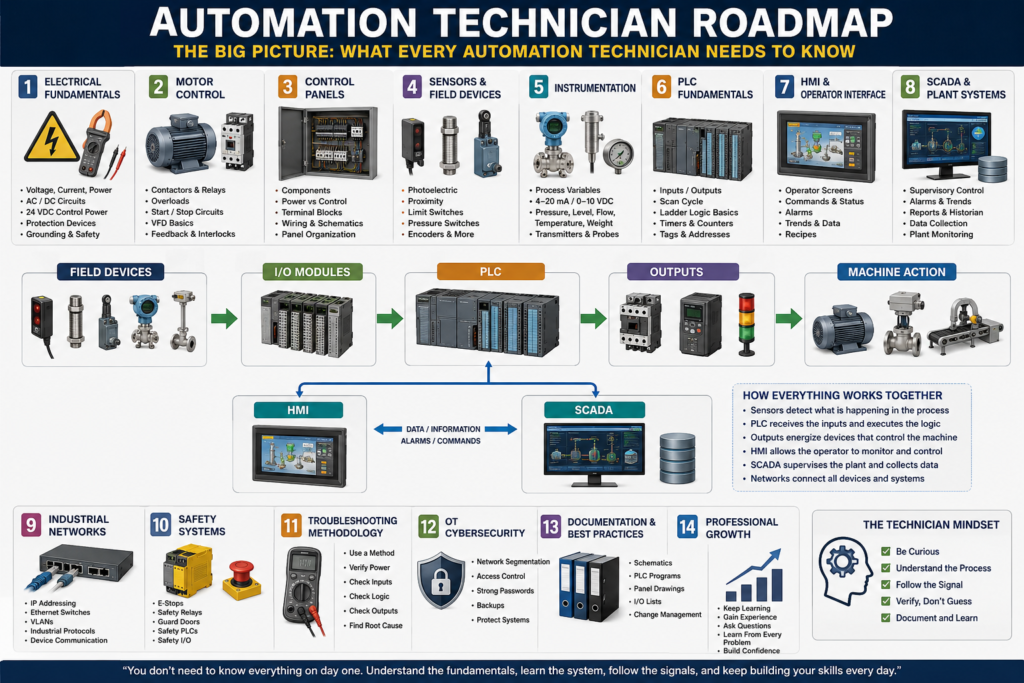
This roadmap is designed to organize the main areas every automation technician should learn, from basic electrical concepts to PLC logic, HMI systems, SCADA, instrumentation, industrial networking, troubleshooting, and OT cybersecurity.
1. Automation Is a Complete System
A machine is not controlled by the PLC alone.
The PLC is important, but it is only one part of a larger system.
A basic industrial automation system usually looks like this:
Field Devices
     ↓
I/O Modules
     ↓
PLC Logic
     ↓
Outputs
     ↓
Machine Action
But in real plants, the system usually includes much more:
Sensors → PLC Inputs → PLC Logic → PLC Outputs → Motors / Valves / Actuators
                         ↓
                        HMI
                         ↓
                       SCADA
                         ↓
                Data / Reports / Network
Each part has a job.
Sensors tell the PLC what is happening.
The PLC makes decisions based on logic.
Outputs energize real devices.
The HMI allows the operator to control and monitor the machine.
SCADA allows higher-level monitoring, data collection, trends, and reports.
Industrial networks connect all these devices together.
When one part fails, the automation technician must understand enough of the system to find where the problem is.
2. Electrical Fundamentals
Before learning PLCs deeply, every automation technician needs a solid foundation in electricity.
This includes:
- Voltage
- Current
- Resistance
- Power
- AC and DC circuits
- 24 VDC control power
- 120 VAC control circuits
- 480 VAC motor power
- Fuses and breakers
- Grounding and bonding
- Electrical safety
In automation, many problems start with basic electrical issues.
A sensor may not work because it has no 24 VDC power.
A relay may not energize because the common is missing.
A motor may not start because an overload is tripped.
A PLC input may not turn on because the signal wire is broken.
Before blaming the PLC program, always verify the electrical basics.
Technician mindset
Ask:
Do I have the correct voltage?
Do I have a complete circuit?
Is the fuse good?
Is the common connected?
Is the device receiving power?
Is the signal reaching the PLC?
A strong automation technician must be comfortable using a multimeter and reading electrical drawings.
3. Industrial Motor Control
Motors are everywhere in industrial automation.
They move conveyors, pumps, fans, mixers, agitators, compressors, fillers, packaging machines, and many other systems.
A technician should understand:
- Contactors
- Motor starters
- Overload relays
- Auxiliary contacts
- Seal-in circuits
- Start/Stop circuits
- Forward/Reverse circuits
- Jogging/Inching
- Motor feedback
- VFDs
A PLC may send a command to start a motor, but the real motor circuit may include a contactor, overload, disconnect, fuses, VFD, safety circuit, and feedback contacts.
That is why motor control is one of the most important areas for an automation technician.
Command vs Feedback
One key concept is the difference between command and feedback.
Command = The PLC is asking the motor to run.
Feedback = Proof that the motor actually started or is available.
Example:
PLC Output ON → Contactor coil energizes → Motor runs → Auxiliary contact confirms feedbackIf the PLC output is ON but the motor does not run, the technician must trace the circuit step by step.
4. Control Panels
The control panel is the heart of the machine’s electrical and automation system.
Inside a control panel, you may find:
- Main disconnect
- Circuit breakers
- Fuses
- 24 VDC power supplies
- PLC chassis or compact PLC
- I/O modules
- Terminal blocks
- Relays
- Contactors
- Overloads
- VFDs
- Safety relays
- Network switches
- Ground bar
- Wire ducts
- Field wiring terminals
A technician must be able to open a panel, identify the components, and understand how power and signals move through the system.
Control circuit vs power circuit
A very important distinction:
Power Circuit = High-power circuit that runs the load.
Control Circuit = Low-power circuit that controls the load.
Example:
24 VDC PLC Output → Relay Coil → Contactor Coil → 480 VAC MotorThe PLC usually does not directly power large motors. It controls devices that control the power circuit.
5. Sensors and Field Devices
Sensors are the eyes and ears of the PLC.
They allow the control system to know what is happening in the real world.
Common industrial sensors include:
- Photoelectric sensors
- Proximity sensors
- Limit switches
- Pressure switches
- Float switches
- Encoders
- Vision sensors
- Temperature probes
- Level sensors
Without reliable sensor feedback, the PLC is blind.
A machine may stop not because the PLC logic is wrong, but because a sensor is dirty, misaligned, broken, disconnected, or wired incorrectly.
Basic sensor troubleshooting
When a PLC input is not turning on, check:
1. Does the sensor have power?
2. Is the sensor LED changing state?
3. Is the signal wire switching?
4. Is the PLC input LED turning on?
5. Is the PLC tag or address changing online?
6. Is the common/0V connected correctly?
This simple method solves many real-world problems.
6. Industrial Instrumentation
Instrumentation is the area of automation focused on measuring process variables.
These include:
- Temperature
- Pressure
- Flow
- Level
- Weight
- Conductivity
- pH
- Speed
- Position
Instrumentation is different from simple ON/OFF sensors because many instruments send analog signals.
Common analog signals include:
4–20 mA
0–10 VDC
1–5 VDC
RTD
Thermocouple
Load cell millivolt signals
A pressure transmitter, for example, may send a 4–20 mA signal to the PLC. The PLC then scales that raw signal into engineering units such as PSI.
Example:
4 mA  = 0 PSI
20 mA = 100 PSI
Instrumentation is critical in process control, batching, filling, heating, cooling, weighing, and quality control.
7. PLC Fundamentals
The PLC is the controller that makes decisions.
It reads inputs, executes logic, and updates outputs.
A basic PLC control path looks like this:
Input Device → PLC Input → PLC Logic → PLC Output → Field DeviceAn automation technician should understand:
- PLC scan cycle
- Inputs and outputs
- Tags and addresses
- Ladder logic
- Timers
- Counters
- Comparators
- One-shots
- Latches and unlatches
- Fault logic
- Alarm logic
- Program routines
- Online troubleshooting
PLC scan cycle
Most PLCs follow this basic cycle:
1. Read inputs
2. Execute logic
3. Update outputs
4. Repeat
This happens very fast, many times per second.
Understanding the scan cycle helps explain why rung order, input buffering, output buffering, and one-shots are important.
8. PLC Logic Design
Writing PLC logic is not only about making something work.
Professional PLC logic should be structured, readable, and easy to troubleshoot.
A clean PLC program may include sections like:
Input Buffering
Mode Selection
Requests
Permissives
Interlocks
Commands
Fault Logic
Alarm Logic
Output Buffering
HMI Status
This structure helps separate different types of logic.
For example:
Permissive
A permissive allows equipment to start.
Motor can start only if:
- E-stop is healthy
- Overload is healthy
- Guard door is closed
- Air pressure is okay
- No active fault exists
Interlock
An interlock stops or blocks equipment when an unsafe or invalid condition occurs.
Stop conveyor if:
- Downstream conveyor is full
- Safety gate opens
- Jam sensor is active
- VFD fault occurs
Fault
A fault is usually a condition that stops the machine or prevents operation.
Motor command is ON, but feedback is missing after 3 seconds.Alarm
An alarm informs the operator that something needs attention.
Low air pressure warning.Understanding these differences makes PLC logic easier to build and troubleshoot.
9. HMI: Human Machine Interface
The HMI is what the operator uses to interact with the machine.
An HMI may include:
- Start/Stop buttons
- Mode selection
- Manual controls
- Machine status
- Alarm banners
- Alarm history
- Production counts
- Recipes
- Trends
- Maintenance screens
- I/O diagnostic screens
The HMI does not control the machine by itself. It communicates with the PLC.
Example:
Operator presses Start on HMI
        ↓
HMI writes Start_Request tag to PLC
        ↓
PLC checks permissives and interlocks
        ↓
PLC starts the machine
A good HMI helps troubleshooting. A poor HMI hides important information.
A strong automation technician should understand both the PLC logic and the HMI screens.
10. SCADA and Plant-Level Systems
SCADA stands for Supervisory Control and Data Acquisition.
SCADA is usually above individual machine HMIs.
It may monitor:
- Multiple machines
- Production lines
- Tanks
- Utilities
- Alarms
- Trends
- Reports
- Energy usage
- Downtime
- Process data
The difference between HMI and SCADA can be simplified like this:
| System | Main Purpose |
|---|---|
| HMI | Local machine operation |
| SCADA | Plant-level monitoring and data collection |
SCADA systems often communicate with PLCs through drivers or OPC UA. They may also store data in historians or SQL databases.
This is where automation begins to connect with IT and data systems.
11. Industrial Networks
Modern automation depends heavily on communication networks.
An automation technician should understand:
- IP addresses
- Subnet masks
- Gateways
- Ethernet switches
- Managed switches
- VLANs
- Fiber connections
- Ring topology
- EtherNet/IP
- Profinet
- Modbus TCP
- Remote I/O
- Network diagnostics
Many modern devices are networked:
PLC
HMI
VFD
Remote I/O
Servo drive
Vision camera
Robot
Barcode scanner
SCADA server
Industrial switch
A machine may be electrically healthy but still fail because communication is lost.
Common network problems
Examples include:
Bad Ethernet cable
Bad RJ45 connector
IP address conflict
Wrong subnet
Wrong gateway
VLAN mismatch
Failed switch port
Device not communicating in PLC I/O tree
Fiber ring issue
This is where IT knowledge becomes very valuable in automation.
12. Safety Systems
Safety systems protect people and equipment.
They are not the same as normal PLC control logic.
Safety systems may include:
- E-stops
- Safety relays
- Safety PLCs
- Guard door switches
- Light curtains
- Safety mats
- Two-hand controls
- Safety-rated outputs
- Dual-channel circuits
- Reset circuits
A standard PLC can monitor safety status, but safety control should be handled by safety-rated devices.
Example:
E-stop pressed
     ↓
Safety relay drops out
     ↓
Motor contactor power is removed
     ↓
PLC receives safety status input
     ↓
HMI displays safety fault
The PLC may display the alarm, but the safety relay or safety PLC is what removes power safely.
13. Troubleshooting Methodology
Troubleshooting is one of the most important skills for an automation technician.
The goal is not to guess.
The goal is to prove where the signal, voltage, command, or condition is lost.
A simple troubleshooting path:
1. Understand the problem
2. Check safety conditions
3. Verify power
4. Check the input device
5. Check the PLC input
6. Check the PLC logic
7. Check the PLC output
8. Check the relay/contactor/VFD
9. Check the field device
10. Document the root cause
Input → Logic → Output method
For PLC troubleshooting, always think:
Input
  ↓
Logic
  ↓
Output
Ask:
Is the PLC seeing the input?
Is the logic allowing the command?
Is the PLC turning on the output?
Is the output device actually working?
This method helps avoid guessing and saves time.
14. OT Cybersecurity
Automation systems are now connected more than ever.
PLCs, HMIs, SCADA servers, drives, switches, and remote access systems may all be part of the OT network.
OT stands for Operational Technology.
OT cybersecurity focuses on protecting industrial systems that control real equipment.
Important concepts include:
- Network segmentation
- VLANs
- Firewalls
- User access control
- Strong passwords
- HMI security
- PLC backups
- HMI backups
- Change control
- USB control
- Remote access control
- Asset inventory
- Incident response
In IT, the main concern is often data.
In OT, the main concern is usually:
Safety
Production uptime
Equipment protection
Process reliability
A cybersecurity issue in OT can stop production or create unsafe conditions.
That is why modern automation technicians need at least a basic understanding of OT cybersecurity.
15. The Automation Technician Mindset
The best automation technicians are not the ones who know everything.
They are the ones who know how to learn, test, verify, and troubleshoot logically.
A strong technician asks good questions:
What changed?
Was this working before?
Is the problem electrical, mechanical, programming, network, or process-related?
Is the PLC seeing the input?
Is the output turning on?
Is a permissive missing?
Is an interlock active?
Is there a fault latched?
Is the HMI showing the real condition?
Automation is learned in layers.
You may start with basic electricity.
Then you learn sensors.
Then motor control.
Then PLC logic.
Then HMI.
Then networks.
Then SCADA.
Then cybersecurity.
Over time, all the pieces begin to connect.
Final Thoughts
Becoming a strong automation technician does not happen overnight.
This field is wide because it combines electrical systems, machines, PLC programming, control panels, instrumentation, networks, HMI, SCADA, safety, and troubleshooting.
At first, it can feel like too much.
But the key is to build the knowledge step by step.
Start with the fundamentals.
Learn how signals move.
Learn how the PLC makes decisions.
Learn how outputs control real devices.
Learn how operators interact with the machine.
Learn how networks connect everything.
Learn how to troubleshoot with a method.
The goal is not to memorize everything.
The goal is to understand how the system works as a whole.
A professional automation technician does not just replace parts.
A professional automation technician understands the system, follows the signal, proves the problem, and fixes the root cause.
This roadmap will guide the rest of the series.