NAMUR Sensors Explained
Operation, Wiring, Diagnostics, and Troubleshooting
Introduction
If you work around hazardous area instrumentation, safety barriers, or process automation systems, you will eventually encounter a device called a NAMUR sensor.
Many technicians initially assume a NAMUR sensor is simply another proximity sensor.
It is not.
A NAMUR sensor operates using a completely different principle than traditional PNP or NPN proximity sensors and is specifically designed for use with intrinsic safety barriers and hazardous locations.
Understanding NAMUR sensors is essential for troubleshooting:
- Pepperl+Fuchs barriers
- MTL barriers
- Intrinsically safe circuits
- Process instrumentation systems
- Hazardous area applications
What Is a NAMUR Sensor?
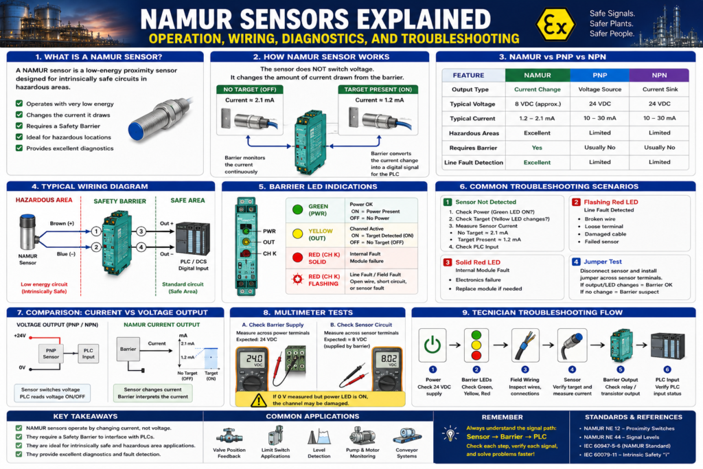
A NAMUR sensor is a low-energy proximity sensor designed to operate in intrinsically safe circuits.
Unlike traditional sensors that switch voltage, a NAMUR sensor changes the amount of current it draws from the barrier.
The barrier monitors this current and determines whether the sensor is ON or OFF.
Why Was NAMUR Developed?
In hazardous areas, the goal is to minimize electrical energy.
Traditional proximity sensors require:
24 VDC
Several milliamps
NAMUR sensors require significantly less energy.
Benefits:
- Reduced ignition risk
- Better intrinsic safety compatibility
- Simpler hazardous area approvals
- Superior fault diagnostics
How a Standard Proximity Sensor Works
PNP Sensor
+24V
  │
Sensor
  │
  └──► PLC Input
Sensor outputs voltage.
PLC detects voltage.
Simple.
How a NAMUR Sensor Works
NAMUR Sensor
Barrier
   │
   │
NAMUR Sensor
   │
   │
Barrier
The sensor does NOT switch voltage.
Instead:
Target Present
↓
Current Changes
↓
Barrier Detects Change
↓
PLC Receives Signal
The barrier interprets the sensor current.
Internal Principle
A NAMUR sensor behaves like a variable load.
No Target
Current ≈ 2.1 mATarget Present
Current ≈ 1.2 mAThe exact values vary slightly by manufacturer.
The barrier monitors this current continuously.
Signal Interpretation
The barrier converts current into a digital state.
Example:
| Sensor Current | Barrier Interpretation |
|---|---|
| > 2 mA | ON |
| < 1.5 mA | OFF |
The barrier then energizes:
- Relay output
- Transistor output
- PLC signal
depending on the module type.
Why Use a Barrier?
A NAMUR sensor cannot connect directly to a PLC input.
A PLC expects:
24VDCA NAMUR sensor provides:
Current ChangeTherefore:
NAMUR Sensor
      ↓
Barrier
      ↓
PLC
The barrier performs signal conversion and intrinsic safety protection.
Typical Wiring
Hazardous Area
NAMUR Sensor
      ↓
Intrinsic Safety Barrier
Safe Area
Barrier Output
      ↓
PLC Input
Complete circuit:
Hazardous Area
      │
NAMUR Sensor
      │
Safety Barrier
      │
PLC Input Card
      │
Safe Area
NAMUR vs PNP vs NPN
| Feature | NAMUR | PNP | NPN |
|---|---|---|---|
| Output Type | Current Change | Voltage Source | Current Sink |
| Typical Voltage | 8 VDC | 24 VDC | 24 VDC |
| Hazardous Areas | Excellent | Limited | Limited |
| Requires Barrier | Yes | Usually No | Usually No |
| Line Fault Detection | Excellent | Limited | Limited |
Advantages of NAMUR Sensors
Intrinsic Safety Compatible
Ideal for:
- Zone 0
- Zone 1
- Zone 2
applications.
Low Power Consumption
Typically operates below:
10 V
15 mA
making ignition extremely unlikely.
Superior Diagnostics
The barrier can detect:
Open Wire
Cable BreakShort Circuit
Conductors TouchingSensor Failure
Internal Sensor FaultMany modern barriers immediately report these conditions.
Understanding Barrier LEDs
Most switch amplifiers provide:
Green LED
Power OKYellow LED
Channel ActiveRed LED
FaultUnderstanding these LEDs is often the fastest troubleshooting method.
Common Troubleshooting Scenario #1
Sensor Not Detected
Symptoms:
Machine Fault
PLC Input OFF
Check:
Step 1
Verify barrier power.
Green LED should be ON.
Step 2
Verify sensor target.
Move metal target into sensing range.
Observe yellow LED.
Step 3
Measure sensor current.
Typical readings:
≈1.2 mA
≈2.1 mA
depending on target state.
Step 4
Check PLC input.
Barrier output should change state.
Common Troubleshooting Scenario #2
Flashing Red LED
Typically indicates:
Line FaultPossible causes:
- Broken wire
- Loose terminal
- Damaged cable
- Failed sensor
Always inspect field wiring first.
Common Troubleshooting Scenario #3
Solid Red LED
Typically indicates:
Internal Barrier FaultPossible causes:
- Electronics failure
- Internal component damage
Module replacement may be required.
Practical Multimeter Test
One of the simplest field tests:
Measure Barrier Supply
Verify:
24 VDCat the barrier.
Measure Sensor Circuit
Many NAMUR barriers provide approximately:
8 VDCto the sensor.
If you measure:
0 Vand power is present,
the barrier or channel may be damaged.
The Jumper Test
Technicians frequently use this method.
Disconnect sensor wiring.
Install temporary jumper across sensor terminals.
Observe:
Yellow LED
Relay Output
PLC Input
Results:
Changes State
Barrier likely good.
Sensor or field wiring suspect.
No Change
Barrier or channel suspect.
Real Industrial Example
Imagine a NAMUR proximity sensor monitoring valve position.
Operator reports:
Valve Open Feedback LostInvestigation:
Green LED
ON
Red LED
Flashing
Yellow LED
OFF
Diagnosis:
Broken cableRepair cable.
Fault clears.
System returns to service.
Common Mistakes
Mistake 1
Connecting a NAMUR sensor directly to a PLC input.
It will not work correctly.
Mistake 2
Treating NAMUR like a PNP sensor.
The operating principle is completely different.
Mistake 3
Ignoring line fault alarms.
Many barriers are telling you exactly where the problem exists.
Mistake 4
Replacing the barrier before checking the sensor.
Field wiring problems are far more common than barrier failures.
Technician Troubleshooting Flow
Power
 ↓
Barrier LEDs
 ↓
Field Wiring
 ↓
Sensor
 ↓
Barrier Output
 ↓
PLC Input
Following this sequence systematically can reduce troubleshooting time dramatically.
Final Thoughts
NAMUR sensors are one of the most common sensor technologies used in hazardous area instrumentation.
Although they appear similar to conventional proximity sensors, they operate using current changes rather than voltage switching and always require a compatible switch amplifier or intrinsic safety barrier.
For automation technicians, learning NAMUR technology is a critical step toward understanding:
- Intrinsic Safety
- Hazardous Area Instrumentation
- Safety Barriers
- Process Control Systems
- Advanced Field Troubleshooting
Mastering NAMUR sensors makes troubleshooting intrinsically safe systems significantly easier and helps bridge the gap between traditional automation and process instrumentation.