3. Instrument Signals: How Field Devices Talk to the PLC
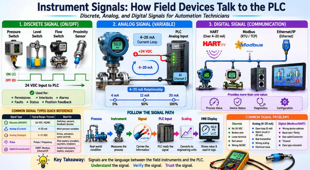
Discrete, Analog, and Digital Signals for Automation Technicians
Industrial instruments measure real-world process conditions such as pressure, level, flow, temperature, weight, pH, or gas concentration. But the PLC cannot directly read those physical conditions.
The PLC needs a signal.
A signal is the way a field device communicates information to the control system.
In simple terms:
An instrument signal is the language used between the field device and the PLC, controller, HMI, or SCADA system.
A pressure transmitter may measure pressure, but the PLC does not directly “see” pressure. The PLC sees a current, voltage, discrete input, pulse, or digital communication value that represents that pressure.
The book Lessons In Industrial Instrumentation covers multiple signal and communication methods used in industry, including discrete I/O, analog I/O, 4–20 mA current loops, HART, Modbus, Ethernet networks, and PLC input/output systems.
Why Instrument Signals Matter
For an automation technician, understanding signals is critical because many troubleshooting problems are not caused by the PLC program itself.
The issue may be:
- A broken wire
- A missing 24 VDC supply
- A failed transmitter
- A bad analog loop
- Wrong scaling
- Electrical noise
- A misconfigured input card
- A communication problem
- A bad HMI tag
A good technician knows how to follow the signal path:
Process → Instrument → Signal → PLC Input → Logic → HMI DisplayIf the HMI value is wrong, the technician must determine whether the problem is in the process, the instrument, the signal, the PLC, the scaling, or the HMI.
The Three Main Types of Instrument Signals
Most field signals can be grouped into three major categories:
| Signal Type | Basic Meaning | Common Example |
|---|---|---|
| Discrete | ON/OFF signal | Pressure switch, level switch, proximity sensor |
| Analog | Variable signal | 4–20 mA pressure transmitter |
| Digital Communication | Data over a protocol | HART, Modbus, Ethernet/IP |
Each type has a different purpose and troubleshooting method.
1. Discrete Signals
A discrete signal has only two states:
ON or OFF
TRUE or FALSE
1 or 0
Energized or De-energized
Discrete signals are used when the PLC only needs to know whether something is present, active, safe, open, closed, high, low, running, or faulted.
Common Discrete Devices
| Device | Example PLC Meaning |
|---|---|
| Pressure Switch | Air pressure OK |
| Level Switch | Tank low level |
| Flow Switch | Flow proven |
| Temperature Switch | High temperature trip |
| Limit Switch | Door fully open |
| Proximity Sensor | Part detected |
| Motor Starter Auxiliary Contact | Motor running feedback |
| Overload Contact | Motor overload tripped |
Example: Pressure Switch
A pressure switch may be wired to a PLC discrete input.
Air Pressure OK Switch → PLC Digital InputThe PLC logic may use it like this:
IF Air_Pressure_OK = TRUE
THEN Machine_Start_Allowed = TRUE
This type of signal is simple, but very important.
A discrete signal is commonly used for:
- Permissives
- Interlocks
- Alarms
- Faults
- Position feedback
- Start/stop logic
- Safety monitoring
- Machine status
Normally Open and Normally Closed Signals
Automation technicians must understand the difference between the field device contact and the PLC logic condition.
A field device may be wired as:
| Contact Type | Meaning |
|---|---|
| Normally Open | Contact closes when the condition is active |
| Normally Closed | Contact opens when the condition is active |
But in the PLC, the logic may be written based on the desired condition:
DI_Air_Pressure_OK
DI_Guard_Closed
DI_Motor_Overload_OK
DI_EStop_OK
This is why naming matters.
A good tag name should describe the healthy or useful condition, not just the electrical contact.
Example:
Good: DI_Air_Pressure_OK
Less Clear: DI_Pressure_Switch
2. Analog Signals
An analog signal changes continuously over a range.
Instead of being only ON or OFF, it represents a process value.
Example:
4–20 mA = 0–100 PSIAnalog signals are used when the PLC needs to know how much pressure, level, flow, temperature, weight, or pH exists.
Common Analog Instruments
| Instrument | Common Signal |
|---|---|
| Pressure Transmitter | 4–20 mA |
| Level Transmitter | 4–20 mA |
| Flow Transmitter | 4–20 mA or pulse |
| Temperature Transmitter | 4–20 mA |
| pH Transmitter | 4–20 mA |
| Weight Transmitter | 4–20 mA or digital |
| Control Valve Positioner | 4–20 mA command |
4–20 mA: The Most Common Analog Signal
The 4–20 mA current loop is one of the most common industrial instrumentation signals.
A typical relationship looks like this:
| Signal | Process Value |
|---|---|
| 4 mA | 0% |
| 12 mA | 50% |
| 20 mA | 100% |
Example:
0 PSI   = 4 mA
50 PSI  = 12 mA
100 PSI = 20 mA
This is useful because the PLC can scale the analog input into engineering units.
4–20 mA → PLC Analog Input → Scaling → PSI, GPM, °F, %, gallonsWhy 4 mA Is Not the Same as 0 mA
This is a very important concept.
In a 4–20 mA signal:
4 mA = 0% process value
0 mA = bad signal condition
A 4 mA signal usually means the process is at the low end of the calibrated range.
A 0 mA signal may mean:
- Open circuit
- Broken wire
- Lost power supply
- Failed transmitter
- Disconnected loop
- Bad analog input connection
This is called a live zero signal.
The signal starts at 4 mA instead of 0 mA so the control system can distinguish between a valid low reading and a failed loop.
Example: Level Transmitter
A level transmitter may be ranged like this:
0% tank level = 4 mA
50% tank level = 12 mA
100% tank level = 20 mA
If the HMI shows 0%, the technician should not immediately assume the tank is empty.
The technician should verify:
- Is the tank actually empty?
- Is the transmitter outputting 4 mA?
- Is the PLC analog input reading correctly?
- Is the scaling correct?
- Is the HMI tag correct?
This is professional troubleshooting.
0–10 VDC Signals
Another analog signal is 0–10 VDC.
This signal is common in some control systems, drives, HVAC equipment, and smaller automation systems.
Example:
0 VDC = 0%
5 VDC = 50%
10 VDC = 100%
However, 0–10 VDC signals are generally more sensitive to voltage drop and electrical noise than 4–20 mA loops, especially over long cable runs.
For process instrumentation, 4–20 mA is usually more common.
RTD and Thermocouple Signals
Temperature measurement may use special sensor signals before they are converted into a standard PLC signal.
RTD
An RTD changes resistance as temperature changes.
Example:
Temperature changes → Resistance changesRTDs are commonly used when accuracy and stability are important.
Thermocouple
A thermocouple generates a very small voltage based on temperature difference.
Example:
Temperature difference → Small millivolt signalThermocouples are often used in high-temperature or rugged applications.
In many industrial systems, the RTD or thermocouple connects to a temperature transmitter. The transmitter then sends a 4–20 mA signal to the PLC.
RTD / Thermocouple → Temperature Transmitter → 4–20 mA → PLC Analog InputPulse Signals
Some instruments send pulse signals instead of a standard analog signal.
Pulse signals are common with:
- Flowmeters
- Encoders
- Speed sensors
- Totalizers
- Metering systems
Example:
Each pulse = a known amount of flowThe PLC may count pulses to calculate:
- Total gallons
- Flow rate
- Speed
- Position
- Production count
Example:
100 pulses = 1 gallonPulse signals are very useful, but the PLC input must be fast enough to capture them correctly.
3. Digital Communication Signals
Some modern instruments communicate digitally using industrial protocols.
Instead of sending only one analog value, a smart device can send multiple pieces of data.
Common Digital Communication Methods
| Communication Type | Common Use |
|---|---|
| HART | Smart transmitters over 4–20 mA loops |
| Modbus RTU | Meters, analyzers, drives, instruments |
| Modbus TCP | Ethernet-based industrial devices |
| Ethernet/IP | PLCs, remote I/O, drives, smart devices |
| Foundation Fieldbus | Process instrumentation networks |
| Profibus PA / DP | Industrial field communication |
HART Communication
HART is important because it allows digital communication over a standard 4–20 mA signal.
A HART transmitter can send:
- Process variable
- Device status
- Diagnostics
- Range values
- Engineering units
- Calibration information
- Configuration data
The analog 4–20 mA signal may still represent the primary process variable, while HART carries additional digital information.
Example:
4–20 mA = Pressure value
HART = Device configuration and diagnostics
Modbus Communication
Modbus is commonly used with:
- Power meters
- Flowmeters
- Analyzers
- VFDs
- Remote I/O
- Temperature controllers
- Weighing systems
Instead of reading one signal wire as ON/OFF or 4–20 mA, the PLC reads data from registers.
Example:
Modbus Register 40001 = Flow Rate
Modbus Register 40002 = Totalized Flow
Modbus Register 40003 = Device Status
With Modbus, troubleshooting includes:
- Device address
- Baud rate
- Parity
- Wiring polarity
- Register address
- Data type
- Word order
- Communication timeout
Ethernet-Based Instrument Signals
Some modern devices communicate over industrial Ethernet.
Examples:
- Ethernet/IP instruments
- Remote I/O blocks
- Smart sensors
- VFDs
- Flowmeters
- Gateways
- Weighing systems
- Vision systems
Ethernet-based devices may provide:
- Process values
- Diagnostic bits
- Alarm status
- Device health
- Configuration parameters
- Control commands
This type of communication is powerful, but it also requires the technician to understand basic networking:
- IP address
- Subnet mask
- Gateway
- Ethernet cable
- Switch port
- Link status
- Device status LEDs
- PLC communication path
Signal Type Comparison
| Signal Type | PLC Reads | Example | Technician Checks |
|---|---|---|---|
| Discrete | ON/OFF | Pressure switch | 24 VDC, input LED, contact state |
| Analog | Variable value | 4–20 mA transmitter | Loop current, power, scaling |
| Pulse | Count/frequency | Flowmeter pulse output | Pulse rate, input speed, wiring |
| Digital | Data/registers | Modbus flowmeter | Address, protocol, data type |
| HART | Digital data over analog loop | Smart transmitter | Loop resistor, communicator, device status |
| Ethernet | Network data | Smart instrument | IP, cable, switch, PLC connection |
How the PLC Uses Instrument Signals
Instrument signals are used in many ways inside the PLC.
Discrete Example
DI_Flow_Proven = TRUEUsed for:
Pump_Running AND NOT Flow_Proven → No_Flow_FaultAnalog Example
AI_Tank_Level_Pct = 65.3%Used for:
IF Tank_Level_Pct < 15%
THEN Low_Level_Alarm = TRUE
Digital Communication Example
Flowmeter.Status = OK
Flowmeter.FlowRate = 45.2 GPM
Flowmeter.Total = 12500 gallons
Used for:
- HMI display
- Batch total
- Production report
- Alarm logic
- Maintenance diagnostics
Common Signal Problems
Instrumentation signal problems are very common in real plants.
Discrete Signal Problems
Possible issues:
- No 24 VDC supply
- Broken wire
- Loose terminal
- Bad sensor
- Wrong sensor alignment
- Failed input card
- Incorrect NO/NC wiring
- Bad input common
- Field device not actuated
Analog Signal Problems
Possible issues:
- Open loop
- Short circuit
- Bad transmitter
- Wrong range
- No loop power
- Bad analog input channel
- Wrong scaling
- Electrical noise
- Poor shield grounding
- Signal out of range
Digital Communication Problems
Possible issues:
- Wrong IP address
- Wrong node address
- Bad cable
- Bad connector
- Incorrect protocol settings
- Termination problem
- Wrong register address
- Timeout
- Data type mismatch
- Device not configured in PLC
Technician Troubleshooting Mindset
When troubleshooting any instrument signal, avoid guessing.
Use a step-by-step method.
Step 1 — Verify the Process
Ask:
Is the real process condition actually what the HMI says?Example:
If the HMI shows low level, check the actual tank, sight glass, local indicator, or field gauge when available.
Step 2 — Verify the Instrument
Ask:
Is the instrument powered, installed correctly, and responding to the process?Check:
- Display
- Status LEDs
- Wiring
- Process connection
- Isolation valves
- Sensor condition
- Device health
Step 3 — Verify the Signal
For discrete:
Measure 24 VDC at the input.For analog:
Measure loop current.For digital:
Check communication status.Step 4 — Verify the PLC Input
Check:
- Input LED
- Raw analog count
- Module status
- Channel status
- Controller tag
- Communication status
Step 5 — Verify Scaling and Logic
Ask:
Is the PLC converting the raw signal correctly?Check:
- Raw minimum
- Raw maximum
- Engineering minimum
- Engineering maximum
- Units
- Alarm limits
- Fault limits
- HMI tag
Practical Example: Pressure Transmitter Signal
Instrument:
PT-101
Range: 0–100 PSI
Output: 4–20 mA
PLC Tag: AI_PT101_Pressure_PSI
Expected signal:
| Pressure | Signal |
|---|---|
| 0 PSI | 4 mA |
| 25 PSI | 8 mA |
| 50 PSI | 12 mA |
| 75 PSI | 16 mA |
| 100 PSI | 20 mA |
If the pressure gauge shows 50 PSI but the HMI shows 0 PSI, the technician should check:
- Does the transmitter display show 50 PSI?
- Is the loop current about 12 mA?
- Is the PLC raw input changing?
- Is the analog card configured correctly?
- Is the scaling correct?
- Is the HMI reading the correct PLC tag?
This method avoids replacing parts unnecessarily.
Practical Example: Flow Switch Signal
Instrument:
FSL-201
Flow Switch Low
Output: 24 VDC discrete input
PLC Tag: DI_Flow_Proven
PLC logic:
IF Pump_Running = TRUE
AND DI_Flow_Proven = FALSE
FOR 10 seconds
THEN No_Flow_Fault = TRUE
If the pump is running but the PLC does not see flow, check:
- Is flow actually present?
- Is the valve open?
- Is the line blocked?
- Is the flow switch adjusted correctly?
- Is 24 VDC present?
- Is the PLC input LED ON?
- Is the PLC tag changing?
- Is the timer logic correct?
Best Practices for Instrument Signals
1. Use Clear Tag Names
Good examples:
DI_Air_Pressure_OK
DI_Flow_Proven
AI_Tank_Level_Pct
AI_Discharge_Pressure_PSI
AI_Product_Temperature_F
Avoid unclear names:
Input_1
Sensor_A
Pressure
Analog_3
2. Separate Raw Inputs from Validated Signals
A professional PLC program should not use raw signals directly everywhere.
Better structure:
Raw Input → Input Buffer → Validated Signal → LogicExample:
Local:1:I.Data.0 → DI_Raw_FlowSwitch → DI_Flow_ProvenFor analog:
Raw Analog Count → Scaled Engineering Value → Validated Process Value3. Add Signal Fault Detection
Analog signals should have fault detection.
Example:
If signal < 3.6 mA → Bad Signal / Under-range
If signal > 21 mA → Bad Signal / Over-range
This helps the PLC detect signal problems instead of treating them as valid process values.
4. Document the Signal Path
For every important instrument, document:
- Instrument tag
- Signal type
- Range
- PLC input card
- Channel
- Engineering units
- HMI tag
- Alarm setpoints
- Calibration information
This makes troubleshooting much faster.
Key Takeaway
Industrial instruments communicate with the PLC through signals.
The main signal types are:
Discrete → ON/OFF condition
Analog → Variable process value
Digital → Data communication
A good automation technician understands not only what the instrument measures, but also how that measurement travels to the PLC and how the PLC uses it.
The professional troubleshooting mindset is:
Do not guess. Follow the signal.Final Thoughts
Instrument signals are the connection between the real world and the automation system.
A sensor or transmitter measures the process. The signal carries that measurement to the PLC. The PLC processes the value, applies logic, triggers alarms, and displays information on the HMI.
Once you understand discrete, analog, and digital signals, industrial instrumentation becomes much easier to troubleshoot.
The next topic in this series will focus on one of the most important industrial signals:
4–20 mA current loopsUnderstanding 4–20 mA is essential for any automation technician working with pressure, level, flow, temperature, pH, weight, and control valves.