8. Control Circuit vs Power Circuit (8 of 13)
Why a Motor Starter Can Be Commanded but the Motor Still Does Not Run
When troubleshooting electrical control panels, one of the most important concepts a technician must understand is the difference between the control circuit and the power circuit.
This is especially important when working with motor starters, contactors, overloads, relays, solenoids, and PLC-controlled equipment.
A common mistake is looking at a motor starter as one simple device. In reality, a motor starter usually has two different electrical paths:
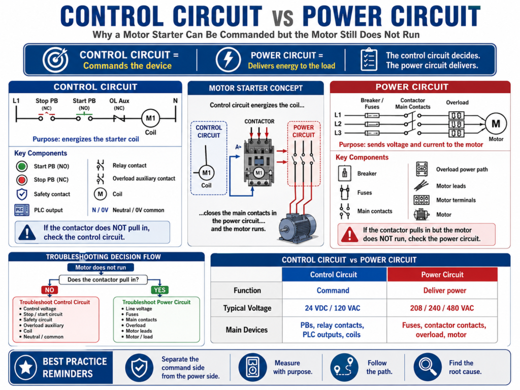
Control Circuit = Commands the device
Power Circuit   = Delivers energy to the load
In simple words:
The control circuit decides.
The power circuit delivers.
Understanding this difference helps a technician troubleshoot faster, safer, and with less guessing.
The TSTrainer Lab Manual explains that control circuits are generally designed so that one circuit controls one machine function, such as starting and stopping a motor, controlling a solenoid valve, or using limit/proximity switches for machine operation.
1. What Is the Control Circuit?
The control circuit is the part of the electrical system that gives the command.
It decides when a device should turn ON or OFF.
Control circuits commonly include:
Start pushbutton
Stop pushbutton
E-Stop contact
Safety relay contact
PLC output
Control relay
Timer contact
Limit switch
Pressure switch
Overload auxiliary contact
Contactor coil
Relay coil
24 VDC or 120 VAC control power
Neutral or 0V common
Example of a basic motor starter control circuit:
L1 → Stop PB NC → Start PB NO → Overload NC → M1 Coil → NeutralIn this example, the contactor coil will energize only if:
Control voltage is present.
The Stop pushbutton is closed.
The Start pushbutton is pressed.
The overload auxiliary contact is closed.
The coil is good.
The neutral/return path is complete.
If any part of this path is open, the contactor coil will not energize.
2. What Is the Power Circuit?
The power circuit is the part of the system that delivers voltage and current to the actual load.
For a motor starter, the power circuit usually includes:
Main disconnect
Circuit breaker
Fuses
Contactor main contacts
Overload power section
Motor leads
Motor terminals
Motor windings
Mechanical load
Example of a three-phase motor power circuit:
L1/L2/L3 → Breaker/Fuses → Contactor Main Contacts → Overload → MotorThe power circuit does not decide when to run. It simply delivers energy when the contactor closes and the power path is healthy.
If the contactor pulls in but the motor does not run, the control circuit may be working, but the power circuit may have a problem.
3. The Key Difference
| Circuit | Main Function | Typical Voltage | Main Components |
|---|---|---|---|
| Control Circuit | Commands the device | 24 VDC, 120 VAC | Pushbuttons, relays, PLC outputs, coils, safety contacts |
| Power Circuit | Feeds the load | 208 VAC, 240 VAC, 480 VAC | Breakers, fuses, contactor contacts, overload, motor leads |
A simple way to remember it:
Control Circuit → Energizes the coil
Power Circuit   → Feeds the motor
The coil is usually part of the control circuit.
The main contacts are part of the power circuit.
4. Example: Motor Starter
A motor starter is the perfect example because it has both circuits.
Control Side
Start command energizes M1 coil.The control circuit pulls in the contactor.
Power Side
Contactor main contacts close and send three-phase voltage to the motor.The power circuit runs the motor.
So when a motor does not run, the first question is:
Does the contactor pull in?That question separates the troubleshooting path.
5. If the Contactor Does Not Pull In
If the contactor does not pull in, focus on the control circuit.
Possible causes:
No control voltage
Blown control fuse
Open Stop pushbutton
Start pushbutton not closing
PLC output not energizing
Safety relay not reset
E-Stop circuit open
Overload auxiliary contact open
Bad contactor coil
Open neutral or 0V common
Loose control wire
Basic troubleshooting steps:
1. Verify control voltage.
2. Measure voltage across the contactor coil.
3. Check the Stop circuit.
4. Check the Start command or PLC output.
5. Check the overload auxiliary contact.
6. Check the safety circuit.
7. Check neutral or 0V common.
Example:
Symptom:
Motor does not start. Contactor does not pull in.

Test:
Measured 0 VAC across M1 coil when Start was pressed.

Next step:
Backtrack through overload contact, Start PB, Stop PB, fuse, and control power source.
This is a control circuit problem until proven otherwise.
The manual emphasizes that troubleshooting should start from the point of failure and backtrack toward the source using the circuit diagram as a guide.
6. If the Contactor Pulls In but the Motor Does Not Run
If the contactor pulls in, the control circuit is probably working.
Now focus on the power circuit.
Possible causes:
Missing line voltage
Blown power fuse
Tripped breaker
Bad contactor main contact
Loose line/load terminal
Open overload power pole
Open motor lead
Local disconnect open
Bad motor winding
Mechanical jam
Phase loss
Basic troubleshooting steps:
1. Verify line voltage into the contactor.
2. Verify voltage leaving the contactor.
3. Verify voltage after the overload.
4. Verify voltage at the motor terminals.
5. Check motor leads and local disconnects.
6. Check motor current if the motor runs.
7. Inspect mechanical load.
Example:
Symptom:
Contactor pulls in, but motor does not run.

Test:
Measured 480 VAC on line side of contactor.
Measured missing phase on load side.

Finding:
One contactor main contact was not passing voltage.
This is a power circuit problem, not a control circuit problem.
7. Control Circuit Example: 120 VAC Starter Coil
Example circuit:
L1 → Control Fuse → Stop PB NC → Start PB NO → OL Aux NC → M1 Coil → NThe coil energizes only when the circuit path is complete.
Expected readings:
| Test Point | Expected Reading |
|---|---|
| L1 to Neutral | 120 VAC |
| After control fuse to Neutral | 120 VAC |
| After Stop PB to Neutral | 120 VAC |
| After Start PB to Neutral | 120 VAC when Start is pressed |
| After OL contact to Neutral | 120 VAC if overload is reset |
| Across M1 coil | 120 VAC when commanded |
If voltage disappears after a device, that device or its wiring becomes suspicious.
For example:
120 VAC before overload contact
0 VAC after overload contact
This suggests the overload auxiliary contact may be open or tripped.
8. Power Circuit Example: Three-Phase Motor
Example circuit:
L1/L2/L3 → Fuses → Contactor → Overload → MotorExpected readings:
| Test Point | Expected Reading |
|---|---|
| Line side of fuses | Correct three-phase voltage |
| Load side of fuses | Correct three-phase voltage |
| Line side of contactor | Correct three-phase voltage |
| Load side of contactor when energized | Correct three-phase voltage |
| After overload | Correct three-phase voltage |
| Motor terminals | Correct three-phase voltage |
For a 480 VAC system, a technician may check:
L1-L2
L2-L3
L1-L3
If one phase is missing after the contactor but present before the contactor, suspect the contactor main contacts or a loose/burned terminal.
9. PLC-Controlled Motor Starter
In modern panels, the control circuit may include a PLC output.
Example:
PLC Output → Interposing Relay → Starter Coilor:
PLC Output → Starter CoilThe PLC may command the starter, but the same separation still applies.
PLC Command Side
Check:
PLC logic
Output LED
Output terminal voltage
Output common
Interposing relay
Safety permissive
Starter coil voltage
Power Side
Check:
Breaker
Fuses
Contactor contacts
Overload
Motor leads
Motor terminals
Motor current
Important point:
PLC output LED ON does not always mean the starter coil has voltage.The output LED may only show that the PLC logic is commanding the output. You still need to verify real voltage at the output terminal and at the coil.
The TSTrainer Lab Manual gives a similar PLC troubleshooting concept: output LEDs may appear to operate, but the actual field devices may not, so the technician must measure the output points and check the power feeding the output section.
10. Common Troubleshooting Mistakes
Avoid these mistakes:
Assuming the motor is bad without testing.
Assuming the contactor is good because it makes noise.
Assuming the PLC output LED proves field voltage.
Checking the control circuit when the power circuit is the problem.
Checking the power circuit when the coil is not being commanded.
Ignoring neutral or 0V common.
Ignoring the overload auxiliary contact.
Only resetting overloads without checking motor current.
Replacing parts without proving the fault.
A professional technician does not troubleshoot by replacing parts.
A professional technician asks:
Is the command present?
Is the coil energized?
Are the contacts closing?
Is voltage reaching the motor?
Is current normal?
What caused the failure?
11. Troubleshooting Decision Table
| Symptom | Likely Area | First Test |
|---|---|---|
| Contactor does not pull in | Control circuit | Measure coil voltage |
| Coil has voltage but no movement | Coil/contactor | Verify coil rating and condition |
| Contactor pulls in but motor dead | Power circuit | Measure line/load voltage |
| Motor runs then trips overload | Motor/load circuit | Measure current on all phases |
| PLC output LED ON but starter OFF | Output/control wiring | Measure voltage at output and coil |
| Contactor chatters | Control voltage/coil | Measure coil voltage while chattering |
| Fuse blows immediately | Power fault/short | Inspect load wiring and motor circuit |
12. Troubleshooting Flow
Use this simple flow:
Motor does not run
       ↓
Does the contactor pull in?
       ↓
NO → Troubleshoot the control circuit
       ↓
YES → Troubleshoot the power circuit
       ↓
Does correct voltage reach the motor?
       ↓
NO → Check fuses, contactor contacts, overload, wiring
       ↓
YES → Check motor, current, overload setting, mechanical load
This keeps the troubleshooting process organized.
13. Practical Example 1: Control Circuit Problem
Symptom:
Motor M1 does not start.

Observation:
Contactor does not pull in.

Expected:
120 VAC should energize M1 coil when Start is pressed.

Testing:
Measured 120 VAC after control fuse.
Measured 120 VAC after Stop PB.
Measured 120 VAC after Start PB when pressed.
Measured 0 VAC after overload auxiliary contact.
Measured 0 VAC across M1 coil.

Finding:
Overload auxiliary contact was open.

Correction:
Inspected overload and found it tripped. Reset overload after checking motor and load.

Root Cause:
Conveyor roller was jammed, causing motor overload.

Final Verification:
Roller was freed. Motor current was checked. M1 started and ran normally.
This is a control circuit issue because the coil never received voltage.
14. Practical Example 2: Power Circuit Problem
Symptom:
Motor M2 does not run.

Observation:
Contactor pulls in when Start is pressed.

Expected:
Three-phase voltage should pass through the contactor and overload to the motor.

Testing:
Measured 480 VAC on line side of contactor.
Measured 480 VAC L1-L2 on load side.
Measured 0 VAC L2-L3 on load side.
Measured 480 VAC L1-L3 on load side.

Finding:
One phase was missing after the contactor.

Correction:
Replaced damaged contactor after proper Lockout/Tagout.

Root Cause:
Loose load-side terminal caused heat damage to one main contact.

Final Verification:
Measured balanced voltage on all three phases. Motor ran normally.
This is a power circuit issue because the coil worked, but the motor power path was faulty.
15. Root Cause Still Matters
Finding whether the problem is on the control side or power side is only part of the job.
You still need to ask:
Why did it happen?
Will it happen again?
What needs to be corrected?
Examples:
| Immediate Fault | Possible Root Cause |
|---|---|
| Blown control fuse | Shorted coil or damaged wire |
| Open overload contact | Motor overcurrent or mechanical jam |
| Burned contactor contact | Loose terminal or excessive current |
| Missing phase | Blown fuse, bad contact, phase imbalance |
| Failed coil | Wrong voltage, overheating, unstable control power |
| Chattering contactor | Low voltage, poor seal-in, loose connection |
The manual highlights the importance of not stopping at the quick fix because the root cause can cause the fault to return later.
16. Final Checklist
[ ] Confirm the symptom.
[ ] Determine if the contactor pulls in.
[ ] If not, troubleshoot the control circuit.
[ ] Verify control voltage.
[ ] Measure voltage across the coil.
[ ] Check Stop, Start, Safety, PLC output, and OL auxiliary contacts.
[ ] Check neutral or 0V common.
[ ] If contactor pulls in, troubleshoot the power circuit.
[ ] Verify line voltage.
[ ] Verify load-side contactor voltage.
[ ] Verify voltage after overload.
[ ] Verify voltage at motor terminals.
[ ] Measure motor current when safe and appropriate.
[ ] Inspect mechanical load.
[ ] Repair safely using LOTO when required.
[ ] Verify operation.
[ ] Find and correct the root cause.
Final Thoughts
Understanding the difference between the control circuit and the power circuit is one of the most important skills in motor starter troubleshooting.
When the motor does not run, do not guess.
First ask:
Is the starter coil being commanded?Then ask:
Is power reaching the motor?If the contactor does not pull in, focus on the control circuit.
If the contactor pulls in but the motor does not run, focus on the power circuit.
This simple separation makes troubleshooting faster, cleaner, and more professional.