14. Sensor Wiring Best Practices for Industrial Control Panels (14 of 15)
Introduction
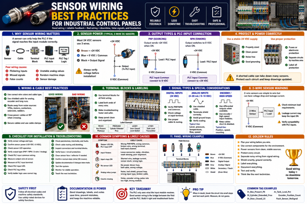
Sensor wiring is one of the most important parts of a reliable industrial control system.
A PLC program can be well written.
The sensor can be the correct model.
The machine logic can be solid.
But if the sensor wiring is poor, the PLC feedback will not be reliable.
Common symptoms of poor sensor wiring include:
PLC input flickering
Sensor LED ON but PLC input OFF
Input works sometimes and fails sometimes
False counts
Intermittent alarms
Analog value jumping
Machine stops randomly
Sensor damage after replacement
Noise problems near VFDs or motors
The Rockwell Automation sensor reference manual explains that the connections between sensors, power supply, and load devices form the electrical interface circuit, and each element is important to the reliability of the application. It also notes that sensors should be powered from a stable, noise-free source and protected from issues like short circuits, overloads, and reverse polarity when possible.
In simple words:
Good wiring creates reliable PLC feedback.
Poor wiring creates unstable machine behavior.
Why Sensor Wiring Matters
Sensors are the field devices that tell the PLC what is happening in the real machine.
Example:
Box present
Door closed
Cylinder extended
Tank level high
Motor running feedback
Label detected
Guard closed
The signal path usually looks like this:
Sensor → Cable → Junction Box / Distribution Block → Control Panel Terminal → PLC Input Module → PLC Tag → Ladder LogicIf any part of this signal path is wrong, the PLC may not receive the correct input.
Important concept:
The PLC does not see the sensor directly.
The PLC only sees the electrical signal that reaches the input module.
That means sensor wiring must be treated as part of the control system, not just a simple connection.
1. Use the Correct Sensor Voltage
Before wiring any sensor, verify the voltage rating.
Common industrial sensor voltages include:
24 VDC
120 VAC
240 VAC
Many modern PLC input circuits use 24 VDC sensors, especially for photoelectric, inductive, capacitive, ultrasonic, and proximity sensors.
A typical 3-wire 24 VDC sensor uses:
Brown = +24 VDC
Blue = 0 VDC / Common
Black = Output signal
Best practice:
Always verify the sensor voltage before installation.Do not assume that all sensors with the same connector use the same voltage.
Example problem:
A 24 VDC sensor is replaced with a 120 VAC sensor.
The connector may look similar, but the sensor will not work correctly with the PLC input.
Or worse:
A 24 VDC PLC input circuit is accidentally connected to 120 VAC.
The input module can be damaged.
2. Use a Stable and Clean Power Supply
Sensors should be powered from a stable control power source.
The Rockwell manual recommends powering switches and sensors from a stable source that is free of noise, typically an isolated line or separate supply, while staying within ratings.
For 24 VDC sensors, use a properly sized industrial power supply.
Check:
Power supply voltage
Power supply current capacity
Fuse or circuit protection
Common connection
Voltage drop
Noise from other devices
Grounding and bonding
Poor sensor power can cause:
Sensor resets
Input flicker
False signals
Analog noise
Intermittent operation
Multiple sensors failing together
Best practice:
Do not overload the 24 VDC power supply.
Do not share sensitive sensor power with noisy loads if avoidable.
Use proper circuit protection.
3. Protect Sensor Circuits with Proper Fusing
Sensor circuits should be protected.
Use:
Properly rated fuses
Electronic circuit protection
Protected distribution blocks
Short-circuit protected sensors when available
Why?
Because sensor cables can be damaged in the field.
Common causes:
Crushed cable
Cut cable
Water in connector
Wrong wiring during replacement
Shorted M12 pin
Damaged junction box
If the sensor circuit is not protected, one short can affect many devices or damage components.
Best practice:
Separate sensor power into protected groups.
Label each fuse or electronic protection channel.
Document which sensors are powered from each circuit.
This makes troubleshooting faster.
4. Match the Sensor Output Type to the PLC Input
Sensor output type must match the input module wiring.
Common output types:
PNP sourcing
NPN sinking
2-wire AC/DC
Relay output
Analog 4–20 mA
Analog 0–10 VDC
IO-Link / network
For 3-wire DC sensors:
PNP = switches +24 VDC to the input
NPN = switches 0 VDC/common to the input
Quick memory:
PNP = Positive output
NPN = Negative output
Best practice:
Always check the sensor wiring diagram and PLC input module wiring diagram.A common problem:
Sensor LED turns ON.
PLC input does not turn ON.
Possible cause:
PNP sensor installed on NPN-style input wiring
or
NPN sensor installed on PNP-style input wiring
or
wrong input common
5. Wire the Input Common Correctly
The input common is one of the most important parts of sensor wiring.
For a PNP sensor:
Sensor output sends +24 VDC to PLC input.
PLC input common usually needs 0 VDC.
For an NPN sensor:
PLC input common usually connects to +24 VDC.
Sensor output provides path to 0 VDC.
If the common is wrong, the circuit is incomplete.
Result:
Sensor output changes,
but the PLC input remains OFF.
Best practice:
Do not guess the input common.
Verify it on the electrical drawing and input module wiring diagram.
6. Use Proper Wire Colors and Cable Standards
For DC 3-wire sensors, common color convention is:
| Wire Color | Function |
|---|---|
| Brown | +24 VDC |
| Blue | 0 VDC / Common |
| Black | Output signal |
| White | Second output, teach, or optional function |
| Gray | Teach, IO-Link, or optional function depending on device |
Important:
This is common, but not universal.
Always verify the datasheet.
For panel wiring, use site or machine standards.
Example:
+24 VDC control power
0 VDC common
Digital input signal wires
Analog signal wires
Shield/drain wires
Safety circuit wires
AC control wires
Best practice:
Follow the site electrical standard.
Do not mix color conventions randomly.
Label wires clearly.
7. Use Terminal Blocks for Clean Panel Wiring
Inside the control panel, sensor wiring should be organized through terminal blocks.
Good terminal blocks help with:
Troubleshooting
Testing
Wire identification
Replacing sensors
Separating field wiring from PLC wiring
Panel cleanliness
Maintenance safety
A good structure:
Field Sensor Cable → Terminal Block → PLC Input ModuleInstead of:
Field Sensor Cable → Directly buried into PLC input terminalDirect wiring to the PLC can work, but terminal blocks usually make maintenance and troubleshooting easier.
Best practice:
Use labeled terminal blocks.
Group sensors by machine area or function.
Keep drawings updated.
8. Label Every Sensor Cable and Terminal
Sensor wiring should be labeled at both ends.
Label:
Sensor device
Cable
Junction box terminal
Panel terminal
PLC input point
Drawing reference
Example labels:
PE101 - Box Present Photoeye
PROX203 - Cylinder Extended Prox
LS301 - Door Closed Limit Switch
LT401 - Tank Level Transmitter
PLC tag examples:
DI_Box_Present_PE
DI_Cylinder_Extended_Prox
DI_Door_Closed_LS
AI_Tank_Level_Pct
Best practice:
The physical device label, drawing name, PLC tag, and HMI description should match as closely as possible.This saves a lot of time during troubleshooting.
9. Route Sensor Cables Away from Noise Sources
Electrical noise can cause unstable sensor signals.
Keep sensor cables away from:
VFD output cables
Motor leads
High-current power conductors
Contactors
Solenoids
Welders
Transformers
High-voltage wiring
Servo motor power cables
Noise can cause:
Input flicker
False counts
Analog value instability
Communication errors
Encoder signal problems
Intermittent alarms
Best practice:
Separate low-voltage sensor wiring from high-voltage power wiring.
Use separate wireways when possible.
Cross power wiring at 90 degrees when crossing is unavoidable.
This is especially important for:
Analog sensors
Encoders
High-speed inputs
IO-Link devices
Long cable runs
Sensors near VFDs
10. Use Shielded Cable When Needed
Some sensor signals require shielded cable.
Shielding is especially important for:
Analog 4–20 mA signals
0–10 VDC signals
Encoders
High-speed counters
Long cable runs
Low-level signals
Noisy environments
Best practice:
Use the cable type recommended by the manufacturer.
Terminate the shield according to the electrical standard.
Avoid grounding both ends unless the design specifically requires it.
For many analog and encoder applications, improper shield termination can create noise problems.
Common symptom:
Analog level value jumps randomly.
Encoder count changes when machine is stopped.
Input flickers when a VFD starts.
Possible cause:
Poor shielding, grounding, or cable routing.11. Be Careful with Analog Sensor Wiring
Analog sensors require extra care.
Common analog signals:
4–20 mA
0–10 VDC
1–5 VDC
RTD
Thermocouple
For PLC analog inputs, verify:
Current or voltage mode
Correct input channel
Correct polarity
Correct scaling
Shielding
Grounding
Loop power
Transmitter power
Signal isolation
A common problem:
Tank level changes,
but HMI stays at 0%.
Possible causes:
Open 4–20 mA loop
Wrong analog card configuration
Wrong channel
Bad scaling
No transmitter power
Broken cable
Wrong polarity
Best practice:
Document the raw range and engineering range.Example:
4 mA = 0% tank level
20 mA = 100% tank level
PLC tags:
AI_Tank_Level_Raw
AI_Tank_Level_mA
AI_Tank_Level_Pct
12. Be Careful with 2-Wire Sensors
2-wire sensors are wired in series with the load or PLC input.
They can have:
Leakage current
Voltage drop
Minimum load requirements
Compatibility issues
The Rockwell manual explains that 2-wire sensors are simple to wire, but their voltage drop and the need to power themselves through the same line they switch can limit performance.
Common symptoms:
PLC input stays ON when sensor is OFF
PLC input flickers
Sensor LED ON but PLC input weak
Input does not turn ON fully
Best practice:
Do not treat a 2-wire electronic sensor exactly like a dry contact.
Check leakage current, voltage drop, and PLC input compatibility.
13. Use Quality Connectors and Distribution Blocks
Many modern machines use:
M8 connectors
M12 connectors
Cordsets
Patchcords
Passive distribution blocks
IO-Link masters
Remote I/O blocks
These make wiring cleaner, but they must be installed correctly.
Check:
Connector pinout
Connector tightness
Water ingress
Bent pins
Oil or chemical damage
Correct cable type
Correct keying
Correct sensor port
Best practice:
Use industrial-rated cordsets.
Use the correct IP-rated connectors for washdown or wet areas.
Do not overtighten or undertighten connectors.
Use protective caps on unused ports.
14. Separate Standard Inputs from Safety Inputs
This is very important.
Standard sensors and standard PLC inputs are not the same as safety-rated devices and safety-rated inputs.
Examples of safety-related devices:
E-stop buttons
Safety gate switches
Safety light curtains
Safety mats
Safety rope pulls
Safety-rated interlock switches
Safety relays
Safety PLC inputs
Best practice:
Do not wire personnel safety functions only into a standard PLC input.
Use proper safety-rated components and circuits.
A standard door closed sensor may be used for HMI status or process logic.
But a guard door used for personnel protection must be designed according to the required safety standards and risk assessment.
15. Document Normal State Clearly
Every sensor should have a documented normal state.
Example:
DI_Door_Closed_LS = ON when door is fully closed
DI_Box_Present_PE = ON when box is present
DI_Photo_Eye_Clear = ON when beam is clear
DI_Air_Pressure_OK = ON when air pressure is healthy
Why this matters:
Technicians need to know what ON means.
HMI indicators must match real-world meaning.
PLC logic becomes easier to read.
Troubleshooting becomes faster.
Avoid unclear descriptions:
Sensor ON
Input active
Switch made
PE1
Better descriptions:
Box Present
Door Closed
Cylinder Extended
Photo Eye Clear
Air Pressure OK
16. Use Input Buffering in PLC Logic
Good wiring should be supported by good PLC structure.
A professional PLC program often uses input buffering:
Physical Input → Buffered Input Tag → Debounced/Validated Tag → Machine LogicExample:
Local:1:I.Data.0 → DI_Box_Present_PE → Box_Present_StableBenefits:
Clear tag names
Easier troubleshooting
Centralized input mapping
Debounce can be applied in one place
Raw inputs are not used everywhere
Logic is easier to maintain
Best practice:
Do not use raw physical input addresses all over the program.
Map them once in an input buffer routine.
17. Use Debounce Only When Needed
Some inputs may need debounce or validation.
Examples:
Mechanical limit switches
Photoeyes with unstable product
Capacitive sensors near splashing or powder
Pressure switches near threshold
Inputs affected by vibration
Debounce concept:
Input must remain ON for a short time before logic accepts it as valid.
Input must remain OFF for a short time before logic accepts it as OFF.
Important:
Debounce should not hide a bad sensor installation.First fix:
Sensor alignment
Sensing distance
Mechanical mounting
Cable issue
Noise problem
Target instability
Then use debounce if the input still needs filtering.
18. Create Useful HMI Diagnostics
Good wiring and good PLC logic should be visible on the HMI.
Useful HMI indicators:
Sensor status
Input status
Device ready
Fault status
Command vs feedback
Timeout faults
Bypass status
Manual/Auto mode
Example HMI status:
Door Closed Limit Switch: ON
Door Open Limit Switch: OFF
Photo Eye Clear: ON
Door Motor Feedback: OFF
Door Fault: None
This helps operators and technicians troubleshoot quickly.
Best practice:
Do not show only “Machine Fault.”
Show which feedback or condition caused the problem.
19. Recommended Sensor Wiring Documentation
A good sensor documentation sheet should include:
Device name
PLC tag
Sensor type
Wiring type
Output type
Voltage
Normal state
PLC input address
Panel terminal
Cable number
Drawing reference
HMI description
Troubleshooting notes
Example:
Device Name:
PE101 Box Present Photoeye

PLC Tag:
DI_Box_Present_PE

Sensor Type:
Photoelectric retroreflective

Wiring Type:
3-wire DC

Output Type:
PNP sourcing

Voltage:
24 VDC

Normal State:
ON when box is present

PLC Input:
Local:1:I.Data.3

Panel Terminal:
TB-DI-103

Cable:
CBL-PE101

PLC Use:
Fill cycle permissive, conveyor stop, jam detection

Troubleshooting:
Check sensor power, reflector alignment, black output wire, PLC input LED, and tag online.
Sensor Wiring Best Practices Checklist
Use this checklist for installation or troubleshooting:
1. Verify sensor voltage.
2. Verify AC or DC type.
3. Verify 2-wire or 3-wire wiring.
4. Verify PNP, NPN, relay, analog, or network output.
5. Check PLC input module compatibility.
6. Confirm input common polarity.
7. Use proper fuse or electronic circuit protection.
8. Use clean and stable power.
9. Label sensor cables and terminals.
10. Use proper terminal blocks.
11. Keep sensor wiring away from high-voltage and VFD cables.
12. Use shielded cable for analog, encoder, and high-speed signals.
13. Terminate shields correctly.
14. Use industrial-rated M8/M12 connectors.
15. Protect unused ports.
16. Document normal state.
17. Map inputs in an input buffer routine.
18. Use debounce only when needed.
19. Show useful diagnostics on the HMI.
20. Keep electrical drawings updated.
Common Wiring Problems and Symptoms
| Symptom | Possible Wiring Cause |
|---|---|
| Sensor LED ON, PLC input OFF | PNP/NPN mismatch, wrong common, broken output wire |
| Input stays ON when sensor OFF | Leakage current, shorted wire, wrong NO/NC logic |
| Input flickers | Loose connector, vibration, noise, weak sensing margin |
| No sensor LED | No power, blown fuse, bad cable, wrong voltage |
| Analog value jumps | Shielding, grounding, noise, wrong input type |
| Encoder misses counts | Wrong input module, noise, poor shield, pulse rate too high |
| Multiple sensors fail | Blown fuse, common power issue, distribution block fault |
| Works after moving cable | Broken conductor or loose connector |
Practical Field Example: Sensor LED ON, PLC Input OFF
Problem:
A photoeye detects a box. The sensor LED turns ON, but the PLC input stays OFF.Troubleshooting:
1. Check brown to blue for 24 VDC.
2. Confirm sensor output type is PNP.
3. Measure black output to blue/common.
4. Confirm black wire sends +24 VDC when ON.
5. Measure voltage at PLC input terminal.
6. Check PLC input common is connected to 0 VDC.
7. Check PLC input LED.
8. Check PLC tag online.
Likely causes:
Wrong common
Broken cable
Wrong sensor output type
Wrong terminal
Bad input channel
Practical Field Example: Analog Level Signal Jumping
Problem:
Tank level on HMI jumps randomly.Possible wiring causes:
Analog cable routed near VFD output cable
Shield not terminated correctly
Loose analog terminal
Wrong analog module configuration
Poor 24 VDC power
Ground loop
Bad transmitter cable
Troubleshooting:
Check raw analog value.
Measure 4–20 mA signal.
Inspect shield and grounding.
Check cable routing.
Verify analog card configuration.
Compare field value to PLC raw value.
Technician Mindset
When wiring or troubleshooting sensors, do not only ask:
Is the sensor connected?Ask:
Is the sensor powered correctly?
Is the signal type correct?
Does the PLC input module match the sensor output?
Is the input common correct?
Is the wiring protected?
Is the cable routed away from noise?
Is the signal shielded if needed?
Is the device labeled clearly?
Does the PLC tag describe the real-world condition?
Is the HMI showing useful feedback?
This mindset separates quick fixes from professional industrial troubleshooting.
Final Thoughts
Sensor wiring is the foundation of reliable PLC feedback.
A sensor can only help the PLC if the signal reaches the input module correctly.
The key takeaway is:
Correct sensor + correct wiring + correct input module + correct documentation = reliable feedback.Poor wiring can create symptoms that look like PLC logic problems:
False faults
Random stops
Input flicker
Missed counts
Unstable analog values
Machine sequence problems
Before blaming the program, verify the signal path:
Sensor power
Sensor output
Cable
Terminal block
PLC input common
PLC input LED
PLC tag
Ladder logic
Good sensor wiring reduces downtime, improves troubleshooting, protects equipment, and makes the control system easier to maintain.