15. Using Sensor Feedback in PLC Logic: Permissives, Interlocks, Faults, and Alarms (15 of 15)
Introduction
Industrial sensors are not installed only to turn a PLC input ON or OFF.
They are installed to give the PLC useful feedback from the real machine.
A sensor can tell the PLC:
A box is present.
A door is fully closed.
A cylinder is extended.
A motor is actually running.
A tank level is high.
A photo eye is clear.
A guard door is closed.
A product is in position.
This feedback is what allows the PLC to make reliable control decisions.
A PLC output command tells the machine what to do.
A sensor feedback signal tells the PLC what actually happened.
The Rockwell Automation sensor reference manual explains that presence sensing technology is used to monitor, regulate, and control industrial processes, and to help verify that critical process steps are completed as intended.
In simple words:
Sensor feedback is the bridge between the physical machine and PLC logic.Why Sensor Feedback Matters
A PLC program should not only command devices. It should also verify that the machine responded correctly.
Example:
PLC Command:
Start conveyor

Expected Feedback:
Motor running feedback turns ON
Another example:
PLC Command:
Close door

Expected Feedback:
Door closed limit switch turns ON
Without feedback, the PLC is only assuming that the output worked.
With feedback, the PLC can prove the machine action happened.
This is the foundation of industrial control logic:
Command → Action → Feedback → DecisionExample:
Door_Close_Command = ON
DI_Door_Closed_LS = ON
Result: Door closed successfully
But if the feedback does not happen:
Door_Close_Command = ON
DI_Door_Closed_LS = OFF
Timer Done = Door Close Timeout Fault
Now the PLC can stop the sequence and alert maintenance or the operator.
The Four Main Ways Sensors Are Used in PLC Logic
Sensor feedback is commonly used in four major logic categories:
1. Permissives
2. Interlocks
3. Faults
4. Alarms
These terms are related, but they do not mean the same thing.
Understanding the difference is very important for writing professional PLC logic.
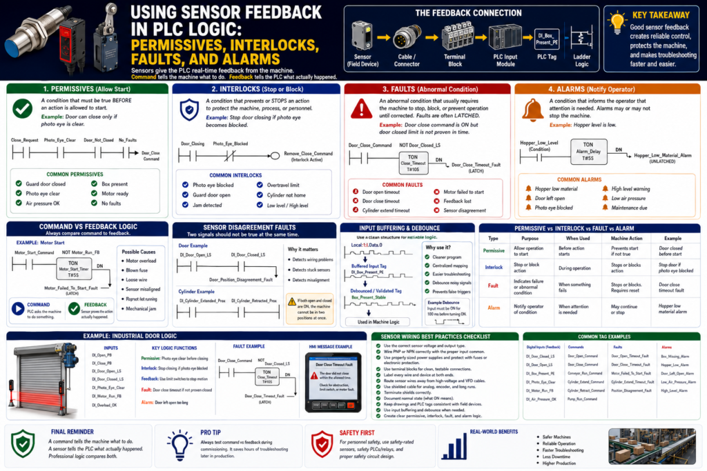
1. Permissives
What Is a Permissive?
A permissive is a condition that must be true before an action is allowed to start.
A permissive does not usually command the action by itself.
It only gives permission.
Simple definition:
Permissive = condition required before startingExample:
The conveyor can start only if the guard door is closed.PLC concept:
Start_Request
AND DI_Guard_Door_Closed
AND No_Faults
= Conveyor_Run_Command
Here, the guard door sensor is a permissive.
It does not start the conveyor by itself.
It only allows the start command to happen.
Common Sensor Permissives
Common permissive inputs include:
DI_Guard_Door_Closed
DI_Air_Pressure_OK
DI_Door_Closed_LS
DI_Photo_Eye_Clear
DI_Box_Present
DI_Motor_Ready
DI_Valve_Home
DI_Cylinder_Retracted
DI_EStop_OK
Examples:
Machine can run only if guard is closed.
Door can close only if photo eye is clear.
Fill cycle can start only if box is present.
Cylinder can extend only if previous cylinder is retracted.
Pump can start only if tank level is not low.
Permissive Ladder Logic Concept
Example: Allow fill cycle only if a box is present.
Rung Purpose:
Allow filling only when a box is present, the station is ready, and no faults are active.

Logic:
DI_Box_Present_PE
AND Station_Ready
AND No_Faults
= Fill_Cycle_Enable
Suggested tags:
DI_Box_Present_PE
Station_Ready
No_Faults
Fill_Cycle_Enable
This is a permissive because the box-present sensor allows the fill sequence to begin.
2. Interlocks
What Is an Interlock?
An interlock is a condition that prevents, blocks, or stops an action to protect the machine, process, or personnel.
Simple definition:
Interlock = condition that prevents or stops an actionExample:
If the photo eye becomes blocked while the door is closing, stop the close command.PLC concept:
Door_Closing
AND Photo_Eye_Blocked
= Remove_Close_Command
An interlock is usually more active than a permissive.
A permissive allows starting.
An interlock can stop or block the action.
Common Sensor Interlocks
Common interlock inputs include:
DI_Photo_Eye_Blocked
DI_Guard_Door_Open
DI_Overtravel_LS
DI_Door_Not_Closed
DI_Cylinder_Not_Home
DI_Jam_Detected
DI_High_Level
DI_Low_Pressure
DI_Motor_Overload
Examples:
Stop conveyor if jam sensor is blocked.
Stop door closing if photo eye is blocked.
Prevent cylinder extend if another mechanism is not retracted.
Stop pump if low-level switch is active.
Prevent machine run if guard door opens.
Important safety note:
If the sensor is part of personnel safety, use safety-rated devices and safety-rated control circuits.
Do not rely only on standard PLC logic for personnel protection.
Interlock Ladder Logic Concept
Example: Stop door close command if photo eye is blocked.
Rung Purpose:
Remove the close command if an obstruction is detected while the door is closing.

Logic:
Door_Close_Command
AND NOT DI_Photo_Eye_Clear
= Close_Interlock_Active
Then:
Close_Request
AND DI_Photo_Eye_Clear
AND No_Faults
AND NOT DI_Door_Closed_LS
= Door_Close_Command
The photo eye can be used in two ways:
As a permissive before closing
As an interlock during closing
That is very common in industrial door logic.
Permissive vs Interlock
| Concept | Meaning | Example |
|---|---|---|
| Permissive | Must be true before action starts | Door can close only if photo eye is clear |
| Interlock | Blocks or stops action | Stop closing if photo eye becomes blocked |
| Permissive question | “Am I allowed to start?” | Is air pressure OK? |
| Interlock question | “Should I stop or block this?” | Did a jam occur? |
Simple memory:
Permissive = permission to start
Interlock = protection during operation
3. Faults
What Is a Fault?
A fault is an abnormal condition that usually requires the machine to stop, block motion, or prevent automatic operation until corrected.
Faults are often latched.
Simple definition:
Fault = abnormal condition that requires correction or resetA fault usually means something failed or did not happen as expected.
Example:
PLC commanded the motor to run,
but motor feedback did not turn ON.
Logic concept:
Motor_Run_Command
AND NOT DI_Motor_Run_FB
AND Timer.DN
= Motor_Failed_To_Start_Fault
This is a command-versus-feedback fault.
Common Sensor-Based Faults
Common sensor fault examples:
Door_Open_Timeout_Fault
Door_Close_Timeout_Fault
Cylinder_Extend_Timeout_Fault
Cylinder_Retract_Timeout_Fault
Motor_Failed_To_Start_Fault
Motor_Feedback_Lost_Fault
Box_Jam_Fault
High_High_Level_Fault
Overtravel_Fault
Sensor_Disagreement_Fault
Faults are often used when:
A movement does not complete.
A feedback signal is missing.
A device runs but feedback is not proven.
Two sensors disagree.
A dangerous or damaging condition occurs.
A timeout expires.
Command vs Feedback Fault Logic
This is one of the most important industrial PLC patterns.
Basic idea:
Command is ON
Expected feedback is OFF
Timer expires
Fault is latched
Example: Door close timeout.
Door_Close_Command
AND NOT DI_Door_Closed_LS
TON Door_Close_Timeout_Timer

Door_Close_Timeout_Timer.DN
OTL Door_Close_Timeout_Fault
This tells the technician:
The PLC tried to close the door,
but the closed limit switch did not prove closed in time.
Possible causes:
Door jammed
Motor failed
VFD fault
Limit switch misaligned
Broken wire
Mechanical obstruction
Overload tripped
Photo eye interlock active
This is very useful because the PLC logic gives maintenance a direction.
Feedback Lost Fault
Another important pattern is feedback lost while running.
Example:
Motor_Run_Command = ON
DI_Motor_Run_FB = ON
Everything is normal.
But then:
Motor_Run_Command = ON
DI_Motor_Run_FB = OFF
The PLC can generate:
Motor_Feedback_Lost_FaultLogic concept:
Motor_Run_Command
AND NOT DI_Motor_Run_FB
TON Motor_Feedback_Loss_Timer

Motor_Feedback_Loss_Timer.DN
OTL Motor_Feedback_Lost_Fault
Use a short delay to prevent nuisance trips from contact bounce or momentary transitions.
Sensor Disagreement Fault
Sometimes two sensors should not be ON at the same time.
Example:
DI_Door_Open_LS = ON
DI_Door_Closed_LS = ON
For a normal door, this is not logical.
The door cannot be fully open and fully closed at the same time.
This could indicate:
Wiring problem
Stuck switch
Bad input
Wrong tag mapping
Mechanical problem
Short circuit
Logic concept:
DI_Door_Open_LS
AND DI_Door_Closed_LS
= Door_Position_Disagreement_Fault
Another example:
DI_Cylinder_Extended_Prox
AND DI_Cylinder_Retracted_Prox
= Cylinder_Position_Disagreement_Fault
This is a very professional diagnostic pattern.
4. Alarms
What Is an Alarm?
An alarm is a condition that informs the operator that something needs attention.
An alarm may or may not stop the machine.
Simple definition:
Alarm = operator notificationExamples:
Low air pressure warning
Tank level high
Hopper material low
Box missing
Sensor dirty
Product not detected
Door left open too long
An alarm is usually for awareness, warning, or action.
A fault is usually more serious and may stop the machine or block operation.
Alarm vs Fault
| Concept | Alarm | Fault |
|---|---|---|
| Purpose | Notify operator | Stop/block/protect |
| Severity | Warning or condition | Abnormal failure |
| Machine action | May continue | Usually stops or prevents action |
| Reset | May clear automatically or require acknowledge | Often requires correction and reset |
| Example | Hopper low material | Motor failed to start |
| HMI behavior | Warning banner/status | Fault banner/reset required |
Simple memory:
Alarm = pay attention
Fault = machine cannot continue normally
Sensor Alarm Example
Example: Hopper low material alarm.
DI_Hopper_Material_Present = OFF
Feeder_Run_Command = ON
Timer Done
= Hopper_Low_Material_Alarm
This alarm tells the operator:
The hopper may need material.The machine may continue for a short time depending on the process.
Sensor Fault Example
Example: Door failed to close.
Door_Close_Command = ON
DI_Door_Closed_LS = OFF
Close_Timeout_Timer.DN = ON
= Door_Close_Timeout_Fault
This fault tells the PLC:
The door did not reach the closed position in time.
Stop or block the next step.
This is more serious than an alarm because the expected machine movement failed.
How Sensors Connect to Machine State
Sensors are often used to determine or validate machine states.
Example door states:
CLOSED
OPENING
OPEN
CLOSING
HALTED
FAULTED
Sensor feedback:
DI_Door_Closed_LS = confirms CLOSED
DI_Door_Open_LS = confirms OPEN
Neither limit switch ON = door is between positions
Both limit switches ON = disagreement fault
State-machine logic concept:
If Door_State = CLOSING
AND DI_Door_Closed_LS = ON
Then Door_State = CLOSED
Fault concept:
If Door_State = CLOSING
AND Door_Close_Timer.DN
AND DI_Door_Closed_LS = OFF
Then Door_State = FAULTED
This makes the program easier to troubleshoot because the machine has clear states.
Example: Industrial Door Logic
Inputs
DI_Open_PB
DI_Close_PB
DI_Stop_OK
DI_Door_Open_LS
DI_Door_Closed_LS
DI_Photo_Eye_Clear
DI_Motor_Run_FB
DI_Overload_OK
Internal Bits
Door_Open_Request
Door_Close_Request
Door_Open_Command
Door_Close_Command
Door_Opening
Door_Closing
Door_Halted
Door_Faulted
No_Faults
Fault Bits
Door_Open_Timeout_Fault
Door_Close_Timeout_Fault
Door_Position_Disagreement_Fault
Motor_Feedback_Lost_Fault
Overload_Fault
Alarm Bits
Door_Left_Open_Alarm
Photo_Eye_Blocked_Alarm
Door_Halted_Alarm
Door Close Permissive
Rung Purpose:
Allow close command only when the door is not already closed, photo eye is clear, stop circuit is healthy, and no faults are active.

Logic:
Close_Request
AND NOT DI_Door_Closed_LS
AND DI_Photo_Eye_Clear
AND DI_Stop_OK
AND No_Faults
= Door_Close_Command
Door Close Interlock
Rung Purpose:
Stop closing if the photo eye becomes blocked.

Logic:
Door_Closing
AND NOT DI_Photo_Eye_Clear
= Close_Interlock_Active
The close command should be removed when this interlock becomes active.
Door Close Timeout Fault
Rung Purpose:
Generate a fault if the door is commanded to close but does not reach the closed limit switch in time.

Logic:
Door_Close_Command
AND NOT DI_Door_Closed_LS
TON Door_Close_Timeout_Timer

Door_Close_Timeout_Timer.DN
OTL Door_Close_Timeout_Fault
Door Position Disagreement Fault
Rung Purpose:
Generate a fault if both open and closed limit switches are ON at the same time.

Logic:
DI_Door_Open_LS
AND DI_Door_Closed_LS
= Door_Position_Disagreement_Fault
Example: Conveyor Logic
Inputs
DI_Start_PB
DI_Stop_OK
DI_Box_Present_PE
DI_Jam_PE_Clear
DI_Motor_Run_FB
DI_Overload_OK
Permissive Logic
Start_Request
AND DI_Stop_OK
AND DI_Jam_PE_Clear
AND DI_Overload_OK
AND No_Faults
= Conveyor_Run_Command
Jam Interlock
Conveyor_Run_Command
AND NOT DI_Jam_PE_Clear
= Conveyor_Jam_Interlock
Motor Failed to Start Fault
Conveyor_Run_Command
AND NOT DI_Motor_Run_FB
TON Motor_Start_Feedback_Timer

Motor_Start_Feedback_Timer.DN
OTL Conveyor_Motor_Failed_To_Start_Fault
Box Missing Alarm
Fill_Cycle_Request
AND NOT DI_Box_Present_PE
= Box_Missing_Alarm
Example: Cylinder Sequence Logic
Inputs
DI_Cylinder_Extended_Prox
DI_Cylinder_Retracted_Prox
DI_Air_Pressure_OK
DI_Guard_Closed
Extend Permissive
Extend_Request
AND DI_Cylinder_Retracted_Prox
AND DI_Air_Pressure_OK
AND DI_Guard_Closed
AND No_Faults
= Cylinder_Extend_Command
Extend Complete Feedback
Cylinder_Extend_Command
AND DI_Cylinder_Extended_Prox
= Cylinder_Extend_Complete
Extend Timeout Fault
Cylinder_Extend_Command
AND NOT DI_Cylinder_Extended_Prox
TON Cylinder_Extend_Timeout_Timer

Cylinder_Extend_Timeout_Timer.DN
OTL Cylinder_Extend_Timeout_Fault
Cylinder Sensor Disagreement Fault
DI_Cylinder_Extended_Prox
AND DI_Cylinder_Retracted_Prox
= Cylinder_Position_Disagreement_Fault
Good PLC Logic Structure
A professional PLC program should organize sensor feedback clearly.
Recommended structure:
1. Input Mapping / Input Buffering
2. Input Debounce / Validation
3. Mode Logic
4. Permissive Logic
5. Interlock Logic
6. Command Logic
7. Feedback / Status Logic
8. Fault Logic
9. Alarm Logic
10. Output Mapping / Output Buffering
This makes the program easier to troubleshoot.
Input Buffering Example
Instead of using raw input addresses everywhere:
Local:1:I.Data.0
Local:1:I.Data.1
Local:1:I.Data.2
Map them to meaningful tags:
DI_Door_Open_LS
DI_Door_Closed_LS
DI_Photo_Eye_Clear
Then use those tags in the program.
Basic structure:
Physical Input → Buffered Tag → Debounced/Validated Tag → Machine LogicExample:
Local:1:I.Data.0 → DI_Box_Present_PE → Box_Present_StableDebounce and Validation
Some sensor inputs may need debounce or validation.
Use debounce for:
Mechanical limit switch bounce
Photoeye chatter
Capacitive sensor splashing
Unstable product detection
Vibration near sensor target
Example:
DI_Box_Present_PE must stay ON for 100 ms
before Box_Present_Stable turns ON.
Logic concept:
DI_Box_Present_PE
TON Box_Present_ON_Debounce

Box_Present_ON_Debounce.DN
= Box_Present_Stable
Important rule:
Debounce should improve signal reliability.
It should not hide a bad sensor installation.
First fix:
Sensor alignment
Sensor distance
Mechanical mounting
Wiring
Noise
Target stability
Then use debounce if needed.
Fault Reset Logic
Faults are often latched and require correction before reset.
A good reset should not clear a fault if the fault condition still exists.
Example:
Reset_PB
AND NOT Active_Fault_Condition
= Reset_Allowed
For a door close timeout fault:
Reset_PB
AND DI_Stop_OK
AND DI_Overload_OK
AND NOT Door_Position_Disagreement_Fault
= Fault_Reset_Allowed
Then:
Fault_Reset_Allowed
OTU Door_Close_Timeout_Fault
Important:
Do not allow reset to hide an active unsafe or abnormal condition.Alarm Acknowledge vs Fault Reset
Alarm acknowledge and fault reset should not always be the same.
Alarm Acknowledge
Alarm acknowledge means:
The operator saw the alarm.It does not always mean the condition is fixed.
Fault Reset
Fault reset means:
The fault condition has been corrected,
and the machine is allowed to attempt operation again.
Example:
Hopper Low Alarm can be acknowledged while material is still low.
Motor Failed To Start Fault should not reset until the issue is corrected.
HMI Display Best Practices
Sensor feedback should be visible and meaningful on the HMI.
Good HMI indicators:
Door Open Limit Switch
Door Closed Limit Switch
Photo Eye Clear
Motor Running Feedback
Air Pressure OK
Box Present
Cylinder Extended
Cylinder Retracted
Good alarm/fault messages:
Door failed to close within allowed time.
Cylinder failed to extend.
Motor command is ON but feedback is missing.
Box missing at fill station.
Photo eye blocked during door close.
Door open and closed limits active at the same time.
Poor messages:
Fault 1
Sensor Error
Input Failed
Machine Fault
Alarm 23
A good message tells the technician where to look.
Suggested Tag Naming
Digital Inputs
DI_Box_Present_PE
DI_Door_Open_LS
DI_Door_Closed_LS
DI_Photo_Eye_Clear
DI_Cylinder_Extended_Prox
DI_Cylinder_Retracted_Prox
DI_Motor_Run_FB
DI_Air_Pressure_OK
DI_Overload_OK
Commands
Door_Open_Command
Door_Close_Command
Conveyor_Run_Command
Cylinder_Extend_Command
Cylinder_Retract_Command
Pump_Run_Command
Permissives
Door_Close_Permissive
Machine_Start_Permissive
Fill_Cycle_Permissive
Pump_Start_Permissive
Interlocks
Door_Close_Interlock
Conveyor_Jam_Interlock
Pump_Low_Level_Interlock
Guard_Open_Interlock
Faults
Door_Open_Timeout_Fault
Door_Close_Timeout_Fault
Motor_Failed_To_Start_Fault
Cylinder_Extend_Timeout_Fault
Position_Disagreement_Fault
Alarms
Box_Missing_Alarm
Hopper_Low_Material_Alarm
Door_Left_Open_Alarm
Photo_Eye_Blocked_Alarm
Low_Air_Pressure_Alarm
Practical Logic Pattern
A clean industrial pattern looks like this:
Request → Permissive → Command → Feedback → Fault/Alarm → OutputExample: Door close.
Operator Close Request
↓
Check close permissives
↓
Set Door Close Command
↓
Energize close output
↓
Monitor Door Closed Limit Switch
↓
If feedback received, stop motion
↓
If timeout expires, latch fault
This structure is easy to troubleshoot because each part has a clear purpose.
Recommended Documentation Format
Example:
Tag Name:
DI_Door_Closed_LS

Device:
Door closed limit switch

Signal Type:
24 VDC digital input

Normal State:
ON when door is fully closed

PLC Use:
Door closed feedback, machine start permissive, close command stop, close timeout fault reset

Related Logic:
Door_Close_Command
Door_Close_Timeout_Fault
Door_State
Machine_Start_Permissive

Troubleshooting:
Check door position, limit switch actuator, wiring, PLC input LED, and tag online.
Another example:
Tag Name:
DI_Motor_Run_FB

Device:
Motor starter auxiliary contact or VFD running feedback

Normal State:
ON when motor is proven running

PLC Use:
Command vs feedback verification, motor failed-to-start fault, HMI motor running status

Fault Logic:
If Motor_Run_Command is ON and DI_Motor_Run_FB does not turn ON within allowed time, latch Motor_Failed_To_Start_Fault.
Common Mistakes
Avoid these common mistakes:
Using raw inputs everywhere in the program
Not documenting what ON means
Using alarms and faults interchangeably
Not using command-vs-feedback timers
Resetting faults while the fault condition is still active
Not showing useful HMI messages
Using debounce to hide poor sensor installation
Not checking sensor disagreement conditions
Using a sensor as a safety device without proper safety-rated design
Naming tags Input_1, Sensor_2, or Fault_3
These mistakes make troubleshooting harder and machine behavior less reliable.
Technician Mindset
When you see a sensor input in ladder logic, do not only ask:
Is the input ON?Ask:
What physical condition does this sensor prove?
Is this input used as a permissive?
Is it used as an interlock?
Is it used for command feedback?
Can it generate a fault?
Can it generate an alarm?
Should it be debounced?
Should it be visible on the HMI?
What happens if this signal never turns ON?
What happens if this signal turns OFF unexpectedly?
That mindset turns basic sensor inputs into professional PLC diagnostics.
Final Thoughts
Sensor feedback is one of the most important parts of industrial PLC logic.
Sensors are not just inputs. They are proof from the machine.
They allow the PLC to decide:
Can I start?
Should I stop?
Did the action complete?
Did something fail?
Should I warn the operator?
Should I latch a fault?
The key takeaway is:
Permissives allow action.
Interlocks block or stop action.
Faults indicate abnormal conditions that usually require correction/reset.
Alarms notify the operator that attention is needed.
A professional PLC program does not only energize outputs.
It verifies feedback, checks conditions, detects failures, and gives clear information to operators and technicians.
Good sensor feedback creates:
Safer operation
Better diagnostics
Faster troubleshooting
Less downtime
Cleaner ladder logic
More reliable machines
The final rule for this series is simple:
A command tells the machine what to do.
A sensor tells the PLC what actually happened.
Professional logic compares both.