3. How to Select the Right Sensor for an Industrial Application (3 of 15)
Introduction
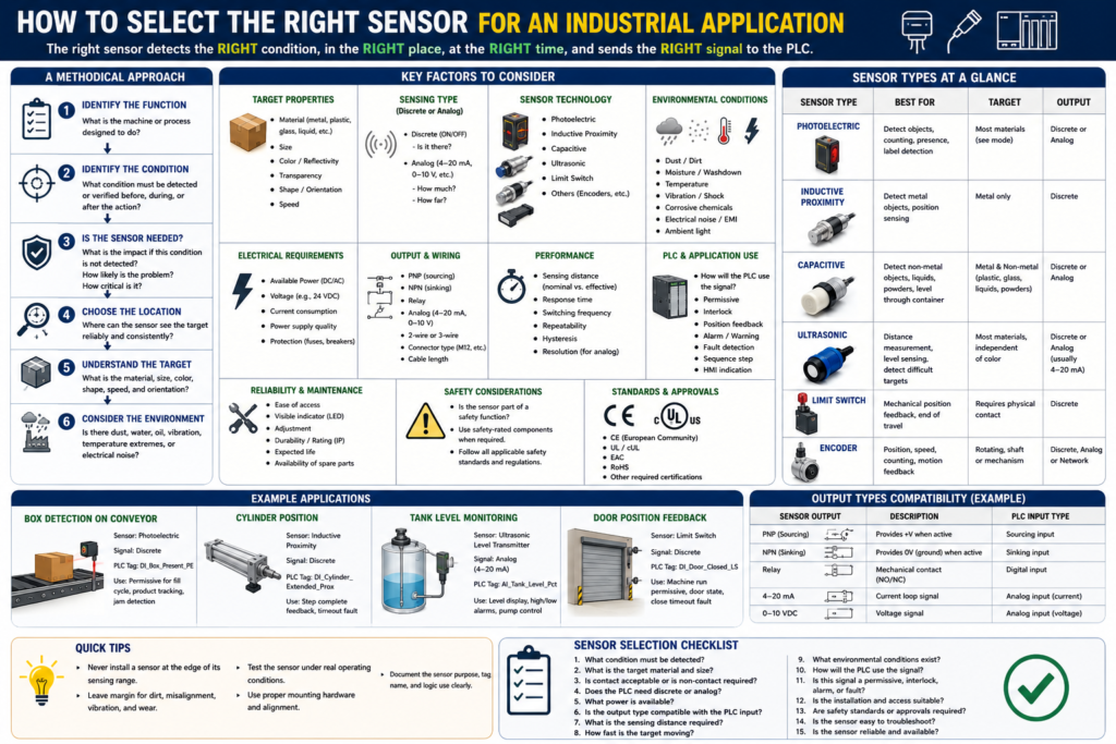
Selecting the right sensor is not just about choosing a device that can detect something.
In industrial automation, the correct sensor must detect the right condition, at the right time, in the right environment, and send a signal that the PLC or control system can use reliably.
A sensor can be installed, powered, and wired correctly, but still fail in the application if it was not selected properly.
For example:
A photoelectric sensor may struggle with a shiny or transparent object.
An inductive proximity sensor will not detect plastic.
A limit switch may wear out if it is hit too hard.
An ultrasonic sensor may give unstable readings if the target surface is angled.
A capacitive sensor may false trigger if product buildup or moisture is present.
This is why sensor selection should be done using a methodical approach.
The Rockwell Automation sensor reference manual explains that sensor selection starts by breaking the system into operations such as fabrication, assembly, packaging, filling, conveying, sorting, indexing, or quality inspection. Then each operation is reviewed to identify which changing conditions must be detected or verified.
In simple words:
Do not select the sensor first.
Understand the application first.
Step 1: Identify the Function of the Machine
The first step is to understand what the machine or process is doing.
Ask:
What is the machine supposed to do?
What operation is happening?
What condition must be verified?
What could go wrong if this condition is not detected?
Examples of machine functions:
Conveying
Filling
Packaging
Sorting
Counting
Indexing
Label detection
Door position control
Cylinder positioning
Tank level monitoring
Product rejection
A sensor should be installed only when it provides useful feedback to the process.
Example:
Function: Filling station
Condition to verify: Box is present before filling
Possible sensor: Photoelectric sensor
PLC feedback: DI_Box_Present_PE
Another example:
Function: Door control
Condition to verify: Door is fully closed
Possible sensor: Limit switch or proximity sensor
PLC feedback: DI_Door_Closed_LS
The sensor must prove something meaningful to the PLC.
Step 2: Identify What Condition Must Be Detected
After identifying the machine function, define the exact condition the sensor must detect.
This is where many mistakes happen.
Do not say only:
We need a sensor here.Be more specific:
We need to detect when a cardboard box is in the filling position.
We need to confirm when the cylinder is fully extended.
We need to detect if a label is missing.
We need to measure the liquid level in the tank.
We need to confirm that a guard door is closed.
The Rockwell manual recommends asking what conditions must be met before a function occurs, what feedback is required during the function, and what conditions must be verified after the function is complete.
A useful format is:
Before the action:
What must be true?

During the action:
What feedback is needed?

After the action:
What proves the action completed correctly?
Example: Cylinder sequence
Before extending:
Guard closed, air pressure OK, no faults.

During extending:
Cylinder is commanded to extend.

After extending:
Cylinder extended sensor must turn ON.
PLC tag example:
DI_Cylinder_Extended_ProxThis signal proves that the cylinder actually reached the extended position.
Step 3: Decide If the Sensor Is Really Needed
Not every point on a machine needs a sensor. A good technician or controls designer chooses sensors based on risk, value, and process reliability.
Ask:
What is the impact if this condition is not detected?
How likely is the problem to occur?
How critical is this condition to process integrity?
The Rockwell manual specifically recommends evaluating the impact of damage or loss, the likelihood of the problem occurring, and how critical the condition is to the process. If any of those are high, then a sensor should be considered.
Example:
If a box is missing and the filler runs anyway:
Product spills.
Machine gets dirty.
Production stops.
Operator must clean the station.
That condition is important. A box-present sensor makes sense.
Another example:
If a door does not prove fully closed:
The machine may run with the door open.
This could create a safety or process risk.
That feedback is critical.
Step 4: Choose the Best Sensing Location
The sensor must be installed where it can detect the condition reliably.
A common mistake is installing a sensor where it is physically convenient, but not where it gives the best feedback.
Ask:
Is this the best place to detect the condition?
Can the sensor see the target consistently?
Is the target stable at this point?
Could vibration, product movement, or misalignment affect detection?
Is there enough space for mounting and adjustment?
Can maintenance access the sensor?
Example:
Bad location:
Photo eye installed where the box is bouncing or shifting.

Better location:
Photo eye installed where the box is guided, stable, and repeatable.
Another example:
Bad location:
Limit switch mounted where a door hits it too hard.

Better location:
Limit switch mounted with correct actuator travel and mechanical protection.
The manual also points out that sometimes the best sensing point is not exactly at the action area. Sometimes detecting the final result, or detecting the object while it is in transit, gives better feedback.
Step 5: Understand the Target
The target is the object or condition the sensor must detect.
Target properties are critical.
Ask:
What material is the target?
Is it metal, plastic, glass, liquid, powder, cardboard, or reflective material?
What color is it?
Is it shiny or dull?
Is it transparent?
How large is it?
How fast is it moving?
Is its position repeatable?
Can it change orientation?
Can it be dirty, wet, damaged, or misaligned?
The Rockwell manual explains that target properties such as size, material, color, and opacity affect the sensor technology choice. For example, inductive sensors detect metal targets, and target size and material can affect sensing range and speed.
Examples:
| Target | Better Sensor Choice |
|---|---|
| Metal bracket | Inductive proximity sensor |
| Cardboard box | Photoelectric sensor |
| Clear bottle | Polarized retroreflective or specialized photoelectric sensor |
| Liquid level | Ultrasonic, capacitive, or level transmitter |
| Door position | Limit switch or proximity sensor |
| Shaft speed | Encoder or proximity sensor |
| Label presence | Photoelectric or vision sensor |
Step 6: Consider the Environment
The environment can make or break a sensor application.
A sensor that works perfectly on a bench may fail in a real production area.
Ask:
Is there dust?
Is there water or washdown?
Is there oil, grease, or product buildup?
Is there vibration?
Is there extreme temperature?
Is there steam or condensation?
Is there electrical noise?
Is there weld field interference?
Is there bright ambient light?
Is the area corrosive?
Is the sensor exposed to impact?
Environmental conditions can affect the sensor’s ability to distinguish the target from the background or surroundings. The Rockwell manual explains that the target, background, and surrounding conditions all influence detection reliability.
Example:
Photoelectric sensor in dusty area:
Lens may become dirty and cause weak signal.

Capacitive sensor near moisture:
May false trigger.

Inductive sensor near weld equipment:
May require weld-field immune type.

Limit switch in freezer:
Ice buildup may prevent actuation.
This is why sensor selection is not only electrical. It is also mechanical and environmental.
Step 7: Decide Between Discrete or Analog
Next, decide what type of signal the PLC needs.
Ask:
Does the PLC only need ON/OFF status?
Or does the PLC need a measured value?
Use a discrete sensor when the question is:
Is it there?
Is it open?
Is it closed?
Is it extended?
Is pressure OK?
Is level high?
Use an analog sensor when the question is:
How full is the tank?
What is the pressure?
How far is the object?
What is the temperature?
What is the position?
Examples:
| Application Need | Signal Type | Example |
|---|---|---|
| Box present | Discrete | DI_Box_Present_PE |
| Door closed | Discrete | DI_Door_Closed_LS |
| Tank level percentage | Analog | AI_Tank_Level_Pct |
| Line pressure PSI | Analog | AI_Line_Pressure_PSI |
| High level only | Discrete | DI_Tank_High_Level |
| Actual level trend | Analog | AI_Tank_Level_Pct |
Important point:
Discrete confirms a state.
Analog measures a value.
Step 8: Check Available Power
Before selecting a sensor, verify the power available in the machine or panel.
Common industrial sensor power:
24 VDC
120 VAC
240 VAC
Many modern PLC sensor circuits use 24 VDC, especially for photoelectric, proximity, ultrasonic, and capacitive sensors.
Ask:
What voltage is available?
Is the supply AC or DC?
Is the power supply stable?
Is the circuit protected by a fuse or breaker?
Is the sensor powered from a clean control power supply?
Is the sensor compatible with the PLC input card?
The Rockwell manual lists common sensor voltage categories such as 10–30V DC, 20–130V AC, 90–250V AC, and 20–250V AC/DC, and recommends using a stable, noise-free power source for sensors.
For PLC work, this matters because a sensor can be the right technology but the wrong electrical version.
Example:
Application needs a 24 VDC PNP sensor.
But a 120 VAC sensor was installed.
Result: It will not interface correctly with the PLC input module.
Step 9: Match the Output Type to the PLC Input
This is one of the most important practical steps.
A sensor output must be compatible with the PLC input module.
Common sensor output types include:
PNP sourcing
NPN sinking
Relay output
Analog 4–20 mA
Analog 0–10 VDC
Network/bus
Ask:
Is the PLC input sinking or sourcing?
Does the machine standard use PNP or NPN?
Is the sensor 2-wire or 3-wire?
Is the analog card configured for current or voltage?
Does the sensor output current exceed the input rating?
Is leakage current a problem?
Example:
PLC input module expects PNP sourcing sensor.
NPN sinking sensor is installed.
The sensor LED may change, but the PLC input may not turn ON correctly.
This is a very common field issue.
Step 10: Check Sensing Distance and Mounting
Sensor range is not just the maximum number on the datasheet.
You must consider the actual installed condition.
Ask:
What is the sensing distance?
Is the sensor too close?
Is the sensor too far?
Is the target always in the same position?
Is the sensor flush or non-flush mountable?
Is there nearby metal?
Is there vibration?
Can the sensor be adjusted?
Important terms:
Nominal sensing distance = rated distance under standard conditions.
Effective sensing distance = real installed sensing distance.
A sensor should not be installed at the very edge of its range if the application needs reliability.
Better practice:
Install the sensor with margin.
Do not depend on perfect conditions.
Step 11: Consider Response Time and Speed
The sensor must be fast enough for the process.
Ask:
How fast is the target moving?
How small is the target?
How long is the target in front of the sensor?
Can the PLC scan see the signal?
Is a pulse stretcher or timer needed?
Example:
A small bottle cap passes a sensor very quickly.
The sensor detects it, but the pulse is too short for the PLC logic or HMI counter.
Possible solutions:
Use a faster sensor.
Move the sensor to a better location.
Use high-speed input if needed.
Use pulse stretching logic.
Use an encoder or specialized inspection device.
Step 12: Think About PLC Logic Use
Before installing the sensor, decide how the PLC will use the signal.
Ask:
Is this sensor a permissive?
Is it an interlock?
Is it position feedback?
Is it used for a fault?
Is it used for an alarm?
Is it only for HMI status?
Is it part of a sequence step?
Example:
DI_Door_Closed_LSPossible PLC uses:
Permissive to allow machine start
Position feedback for door state
Interlock if door opens during operation
Fault if close command is active but feedback never turns ON
HMI indicator for Door Closed
A sensor should not be added only as an input. It should have a clear purpose in the control strategy.
Step 13: Plan for Troubleshooting and Maintenance
A good sensor installation should be easy to troubleshoot.
Ask:
Can the technician see the sensor LED?
Can the sensor be accessed safely?
Is the cable labeled?
Is the PLC tag name clear?
Is the HMI status clear?
Can the sensor be adjusted without major disassembly?
Is the connector standard, such as M12?
Is there a spare part available?
Good PLC tag names:
DI_Box_Present_PE
DI_Label_Detected_PE
DI_Door_Open_LS
DI_Door_Closed_LS
DI_Cylinder_Extended_Prox
AI_Tank_Level_Pct
AI_Line_Pressure_PSI
Poor tag names:
Sensor1
Input_5
PE_A
Switch2
Clear naming helps maintenance troubleshoot faster.
Practical Sensor Selection Examples
Example 1: Detecting a Box on a Conveyor
Application:
Detect cardboard box presence before filling.Questions:
Is the target metal? No.
Is contact acceptable? No.
Does PLC need ON/OFF? Yes.
Is the object moving? Yes.
Good choice:
Photoelectric sensorPLC tag:
DI_Box_Present_PELogic use:
Permissive for fill cycle
Product tracking
Jam detection
Example 2: Detecting a Metal Cylinder Position
Application:
Confirm pneumatic cylinder is fully extended.Questions:
Is the target metal? Yes.
Is the position repeatable? Yes.
Does PLC need ON/OFF? Yes.
Good choice:
Inductive proximity sensorPLC tag:
DI_Cylinder_Extended_ProxLogic use:
Step complete feedback
Timeout fault
Sequence transition
Example 3: Measuring Tank Level
Application:
Display tank level percentage on HMI.Questions:
Does PLC need actual value? Yes.
Is the material liquid? Yes.
Is non-contact preferred? Maybe.
Good choices:
Ultrasonic level sensor
Pressure level transmitter
Radar level sensor
Capacitive level sensor depending on material and tank
PLC tags:
AI_Tank_Level_Raw
AI_Tank_Level_Pct
Logic use:
HMI display
High-level alarm
Low-level alarm
Pump permissive
Trend
Example 4: Confirming Door Fully Closed
Application:
Confirm an industrial door is fully closed.Questions:
Is it mechanical position? Yes.
Does PLC need ON/OFF? Yes.
Is the environment harsh? Possibly.
Is safety involved? Possibly.
Possible choices:
Limit switch
Inductive proximity sensor with metal target
Safety-rated switch if used for personnel safety
PLC tag:
DI_Door_Closed_LSLogic use:
Machine run permissive
Door state feedback
Close timeout fault
HMI indication
Important:
If the sensor is part of a safety function, use proper safety-rated components and follow applicable safety standards. Do not rely on standard PLC logic alone for personnel safety.Sensor Selection Checklist for Technicians
Use this checklist before selecting or replacing a sensor:
1. What condition must be detected?
2. Is the sensor detecting presence, position, level, pressure, distance, speed, or quality?
3. Is the target metal, plastic, glass, liquid, powder, cardboard, transparent, shiny, or dark?
4. Is contact acceptable, or must the sensor be non-contact?
5. Does the PLC need discrete ON/OFF or analog value?
6. What power is available?
7. What output type is required by the PLC input card?
8. What is the sensing distance?
9. How fast is the target moving?
10. What environmental conditions exist?
11. Is the sensor exposed to impact, vibration, moisture, dust, washdown, or temperature extremes?
12. How will the PLC use the signal?
13. Is this a permissive, interlock, alarm, fault, sequence step, or HMI indication?
14. Can maintenance access and troubleshoot the sensor easily?
15. Is the sensor safety-rated if used for personnel protection?
Recommended PLC Documentation Format
When documenting a sensor in a PLC program or maintenance sheet, include:
Tag Name:
DI_Box_Present_PE

Sensor Type:
Photoelectric sensor

Signal Type:
Discrete 24 VDC input

Normal State:
ON when box is present

PLC Use:
Permissive for fill cycle, product tracking, jam detection

Failure Effect:
Fill cycle will not start or may generate box missing alarm

Troubleshooting:
Check sensor LED, alignment, reflector, power, cable, PLC input LED, and input tag online.
This type of documentation makes the program easier to maintain.
Technician Mindset
A professional technician does not only ask:
What sensor do I need?A professional technician asks:
What condition am I trying to prove?
What does the PLC need to know?
What could make this detection unreliable?
What happens if this signal fails?
How will maintenance troubleshoot this later?
That mindset leads to better sensor selection, better PLC logic, and better machine reliability.
Final Thoughts
Selecting the right sensor is a process. It requires understanding the machine function, the target, the environment, the PLC input requirements, and the control logic purpose.
The wrong sensor may still turn ON and OFF, but it may not be reliable in the real application.
The best sensor is not always the most expensive sensor. The best sensor is the one that provides reliable feedback for the condition the PLC needs to verify.
A good rule for PLC technicians is:
Do not select a sensor only by part number.
Select it by application.
Understand the process first.
Then choose the sensor.
That is how sensor feedback becomes reliable industrial control.