How to Represent Machine State in Ladder Logic
RSLogix 500 and Studio 5000 Examples
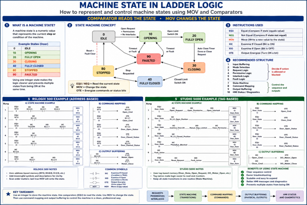
In industrial PLC programming, a machine state is a numeric value that tells the program what step or condition the machine is currently in.
Instead of using many separate latch bits like:
Door_Opening
Door_Closing
Door_Open
Door_Closed
Door_Faulted
a more professional approach is to use one integer value to represent the current state.
For example:
0   = IDLE
10  = OPENING
20  = FULLY_OPEN
30  = CLOSING
40  = FULLY_CLOSED
80  = STOPPED
90  = FAULTED
This method is commonly called a state machine.
The basic rule is simple:
Comparators read the current state.
MOV instructions change the current state.
1. The Main Concept
A state machine uses one main register or tag to store the active state.
In RSLogix 500
You may use an integer address:
N7:0 = Door_StateExample values:
N7:0 = 0   IDLE
N7:0 = 10  OPENING
N7:0 = 20  FULLY_OPEN
N7:0 = 30  CLOSING
N7:0 = 40  FULLY_CLOSED
N7:0 = 80  STOPPED
N7:0 = 90  FAULTED
In Studio 5000
You may create a tag:
Door_State : DINTExample values:
Door_State = 0   IDLE
Door_State = 10  OPENING
Door_State = 20  FULLY_OPEN
Door_State = 30  CLOSING
Door_State = 40  FULLY_CLOSED
Door_State = 80  STOPPED
Door_State = 90  FAULTED
2. MOV vs Comparator
This is the most important part.
| Instruction | Purpose |
|---|---|
EQU | Checks if the current state equals a value |
NEQ | Checks if the current state does not equal a value |
MOV | Writes a new value into the state tag/register |
OTE | Energizes a command or status bit |
XIC | Checks if a bit is ON |
XIO | Checks if a bit is OFF |
Simple Rule
EQU = “Am I in this state?”
MOV = “Go to this state.”
Example:
EQU Door_State 0means:
Is the door in IDLE state?Example:
MOV 10 Door_Statemeans:
Change the door state to OPENING.3. Recommended Door State Codes
For an industrial door example, you can define the states like this:
| State Code | State Name | Meaning |
|---|---|---|
| 0 | IDLE | Waiting for a request |
| 10 | OPENING | Door is opening |
| 20 | FULLY_OPEN | Door is fully open |
| 30 | CLOSING | Door is closing |
| 40 | FULLY_CLOSED | Door is fully closed |
| 80 | STOPPED | Door movement was stopped |
| 90 | FAULTED | Door is in fault condition |
4. Why Use Numbers Like 0, 10, 20, 30?
You may ask:
Why not use 1, 2, 3, 4?
Using numbers like 0, 10, 20, and 30 leaves space to add future states later.
Example:
10 = OPENING
15 = OPENING_SLOW_SPEED
20 = FULLY_OPEN
This makes the program easier to expand.
5. RSLogix 500 Example
In RSLogix 500, you can use an integer file such as N7.
Example:
N7:0 = Door_StateYou can add a symbol/comment to make it easier to understand:
N7:0 Door_StateThen you use EQU instructions to check the state and MOV instructions to change the state.
6. RSLogix 500 State Machine Example
Rung 1 — IDLE to OPENING
EQU N7:0 0
XIC B3:0/0     Open_Request
XIC B3:0/1     Open_Permissive
XIO B3:0/2     Open_Interlock
MOV 10 N7:0
Meaning
If the door is currently idle, there is an open request, the open permissive is true, and there is no open interlock, move the door state to 10, which means OPENING.
Rung Comment
If door is IDLE and an open request is allowed, transition to OPENING state.Rung 2 — OPENING to FULLY_OPEN
EQU N7:0 10
XIC B3:1/0     DI_LS_Open_Position
MOV 20 N7:0
Meaning
If the door is opening and the open limit switch turns ON, move the door state to 20, which means FULLY_OPEN.
Rung Comment
When the open limit switch is made, transition from OPENING to FULLY_OPEN.Rung 3 — FULLY_OPEN to CLOSING
EQU N7:0 20
XIC T4:0/DN    AutoClose_Timer_Done
XIO B3:1/1     Manual_Stop_Latched
XIC B3:0/3     Close_Permissive
MOV 30 N7:0
Meaning
If the door is fully open, the auto-close timer is done, manual stop is not latched, and the close permissive is true, move the door state to 30, which means CLOSING.
Rung Comment
When auto-close conditions are satisfied, transition from FULLY_OPEN to CLOSING.Rung 4 — CLOSING to FULLY_CLOSED
EQU N7:0 30
XIC B3:1/2     DI_LS_Closed_Position
MOV 40 N7:0
Meaning
If the door is closing and the closed limit switch turns ON, move the door state to 40, which means FULLY_CLOSED.
Rung Comment
When the closed limit switch is made, transition from CLOSING to FULLY_CLOSED.Rung 5 — CLOSING to OPENING on Photo Eye Blocked
EQU N7:0 30
XIC B3:1/3     PhotoEye_Blocked
MOV 10 N7:0
Meaning
If the door is closing and the photo eye is blocked, move the door state back to 10, which means OPENING.
This is typical industrial door behavior.
Rung Comment
If the photo eye is blocked while closing, reverse the sequence back to OPENING.Rung 6 — Any State to FAULTED
XIC B3:2/0     Fault_Active
MOV 90 N7:0
Meaning
If any active fault is present, force the door state to 90, which means FAULTED.
Rung Comment
If any fault is active, force the state machine into FAULTED state.Rung 7 — Reset from FAULTED to IDLE
EQU N7:0 90
XIC B3:2/1     Reset_Request
XIO B3:2/0     Fault_Active
MOV 0 N7:0
Meaning
If the door is faulted, the reset request is active, and the fault condition is clear, move the door state back to 0, which means IDLE.
Rung Comment
After faults are cleared and reset is pressed, return the sequence to IDLE.7. RSLogix 500 Command Mapping
After the state machine changes N7:0, use comparators to generate commands.
Open Command
EQU N7:0 10
OTE B3:3/0     Open_Cmd
Meaning
If N7:0 = 10, the door is in the OPENING state, so energize Open_Cmd.
Close Command
EQU N7:0 30
OTE B3:3/1     Close_Cmd
Meaning
If N7:0 = 30, the door is in the CLOSING state, so energize Close_Cmd.
Stop Command / Stopped Status
EQU N7:0 80
OTE B3:3/2     Door_Stopped_Status
Faulted Status
EQU N7:0 90
OTE B3:3/3     Door_Faulted_Status
8. RSLogix 500 Output Buffering
The command bits should then control the physical outputs in the output routine.
XIC B3:3/0     Open_Cmd
OTE O:2/0      Motor_Open_Output
XIC B3:3/1 Close_Cmd
OTE O:2/1 Motor_Close_OutputThis keeps the logic clean:
State Machine → Command Mapping → Output Buffering9. Studio 5000 Example
In Studio 5000, the same concept is cleaner because you can use descriptive tag names.
Create a tag:
Door_State : DINTOptional related tags:
Open_Request
Open_Permissive
Open_Interlock
Close_Permissive
Fault_Active
Reset_Request
DI_LS_Open_Position
DI_LS_Closed_Position
PhotoEye_Blocked
Open_Cmd
Close_Cmd
10. Studio 5000 State Machine Example
Rung 1 — IDLE to OPENING
EQU Door_State 0
XIC Open_Request
XIC Open_Permissive
XIO Open_Interlock
MOV 10 Door_State
Rung Comment
If door is IDLE and an open request is allowed, transition to OPENING state.Rung 2 — OPENING to FULLY_OPEN
EQU Door_State 10
XIC DI_LS_Open_Position
MOV 20 Door_State
Rung Comment
When the open limit switch is made, transition from OPENING to FULLY_OPEN.Rung 3 — FULLY_OPEN to CLOSING
EQU Door_State 20
XIC AutoClose_Timer.DN
XIO Manual_Stop_Latched
XIC Close_Permissive
MOV 30 Door_State
Rung Comment
When auto-close conditions are satisfied, transition from FULLY_OPEN to CLOSING.Rung 4 — CLOSING to FULLY_CLOSED
EQU Door_State 30
XIC DI_LS_Closed_Position
MOV 40 Door_State
Rung Comment
When the closed limit switch is made, transition from CLOSING to FULLY_CLOSED.Rung 5 — CLOSING to OPENING on Photo Eye Blocked
EQU Door_State 30
XIC PhotoEye_Blocked
MOV 10 Door_State
Rung Comment
If the photo eye is blocked while closing, reverse the sequence back to OPENING.Rung 6 — Any State to FAULTED
XIC Fault_Active
MOV 90 Door_State
Rung Comment
If any fault is active, force the state machine into FAULTED state.Rung 7 — Reset from FAULTED to IDLE
EQU Door_State 90
XIC Reset_Request
XIO Fault_Active
MOV 0 Door_State
Rung Comment
After faults are cleared and reset is pressed, return the sequence to IDLE.11. Studio 5000 Command Mapping
Commands should be created after the state machine.
Open Command
EQU Door_State 10
OTE Open_Cmd
Close Command
EQU Door_State 30
OTE Close_Cmd
Door Fully Open Status
EQU Door_State 20
OTE Door_Fully_Open_Status
Door Fully Closed Status
EQU Door_State 40
OTE Door_Fully_Closed_Status
Door Faulted Status
EQU Door_State 90
OTE Door_Faulted_Status
12. Studio 5000 Output Buffering
After command mapping, the output buffer energizes the real outputs.
XIC Open_Cmd
OTE DO_Motor_Open
XIC Close_Cmd
OTE DO_Motor_CloseIf using physical module tags, it may look like this:
XIC DO_Motor_Open
OTE Local:2:O.Data.0
XIC DO_Motor_Close
OTE Local:2:O.Data.1The exact addressing depends on the controller and I/O configuration.
13. Important Difference Between RSLogix 500 and Studio 5000
RSLogix 500
RSLogix 500 uses address-based memory.
Examples:
N7:0
B3:0/0
T4:0/DN
O:2/0
I:1/0
You can add symbols and descriptions to make the logic easier to read.
Example:
N7:0 = Door_State
B3:0/0 = Open_Request
B3:3/0 = Open_Cmd
Studio 5000
Studio 5000 uses tag-based memory.
Examples:
Door_State
Open_Request
Open_Cmd
DI_LS_Open_Position
DO_Motor_Open
This makes the program more readable because the tag name describes the function directly.
14. Side-by-Side Comparison
| Concept | RSLogix 500 | Studio 5000 |
|---|---|---|
| State register | N7:0 | Door_State : DINT |
| Open request | B3:0/0 | Open_Request |
| Open permissive | B3:0/1 | Open_Permissive |
| Open interlock | B3:0/2 | Open_Interlock |
| Open command | B3:3/0 | Open_Cmd |
| Open output | O:2/0 | DO_Motor_Open |
| Auto-close timer done | T4:0/DN | AutoClose_Timer.DN |
| Compare state | EQU N7:0 10 | EQU Door_State 10 |
| Change state | MOV 10 N7:0 | MOV 10 Door_State |
15. Example Routine Structure
A professional program could use this routine order:
1. Input_Buffering
2. Mode_Selection
3. Request_Logic
4. Permissive_Logic
5. Interlock_Logic
6. Fault_Logic
7. Door_State_Machine
8. Command_Mapping
9. Output_Buffering
10. HMI_Status
The state machine should not be mixed randomly with the output logic.
A clean structure is:
Requests + Permissives + Interlocks + Faults
        ↓
State Machine
        ↓
Command Mapping
        ↓
Output Buffering
        ↓
HMI Status
16. Why Not Use Only Latch Bits?
You can create a sequence using latch and unlatch bits, especially in RSLogix 500 or LogixPro.
Example:
Door_Opening_Latch
Door_Closing_Latch
Door_Faulted_Latch
This can work, but there is a risk:
More than one state bit may become ON at the same time.For example:
Door_Opening = ON
Door_Closing = ON
That creates confusion and can become unsafe if not handled correctly.
Using one integer state reduces that problem because the machine has one main state value.
17. Best Practice: One Active State
The goal is:
One device
One current state
Clear transitions
Clear commands
Clear status
For example:
Door_State = 10means only one main thing:
Door is opening.Then you use that state to generate commands and HMI messages.
18. Best Practice: Put Transitions in One Routine
All state transitions should be in one place.
Good:
Routine: Door_State_MachineThis routine handles:
IDLE to OPENING
OPENING to FULLY_OPEN
FULLY_OPEN to CLOSING
CLOSING to FULLY_CLOSED
CLOSING to OPENING
ANY STATE to FAULTED
FAULTED to IDLE after reset
Avoid spreading state transitions across many routines.
Bad:
Some MOV instructions in Requests
Some MOV instructions in Fault Logic
Some MOV instructions in Output Buffering
Some MOV instructions in HMI Status
That makes troubleshooting harder.
19. Best Practice: Use Fault Priority
In many machines, faults should have priority over normal transitions.
For example:
Fault_Active → MOV 90 Door_StateThis should usually override normal operation.
However, you must be careful in ladder scan order. If another rung later in the same scan also writes a different state, it may overwrite the fault state.
20. Important Scan Order Warning
In ladder logic, the PLC scans from top to bottom.
If you write to the same state tag multiple times in one scan, the last true MOV may win.
Example:
Rung 1: Fault_Active MOV 90 Door_State
Rung 10: Close_Request MOV 30 Door_State
If both rungs are true during the same scan, the final state may become 30 if Rung 10 executes after Rung 1.
That can be a problem.
Safer Approach
Place fault override logic near the end of the state transition section, or make sure normal transitions are blocked when a fault is active.
Example:
EQU Door_State 20
XIC AutoClose_Timer.DN
XIO Fault_Active
MOV 30 Door_State
And then:
XIC Fault_Active
MOV 90 Door_State
This helps ensure the machine goes to FAULTED when a fault is active.
21. Optional Professional Improvement: Next State
A more advanced method is to use two tags:
Door_State
Door_Next_State
The logic first calculates the next state, then moves it into the current state.
Example:
Door_State = current active state
Door_Next_State = desired next state
At the end of the state machine:
MOV Door_Next_State Door_StateThis can make complex sequences cleaner, but for basic and intermediate ladder logic, using MOV directly into Door_State is easier to understand.
22. HMI Status from State Codes
The state value can be used to display clear messages on the HMI.
Example:
| Door_State | HMI Message |
|---|---|
| 0 | Door Idle |
| 10 | Door Opening |
| 20 | Door Fully Open |
| 30 | Door Closing |
| 40 | Door Fully Closed |
| 80 | Door Stopped |
| 90 | Door Faulted |
This is much better than showing only raw inputs.
Instead of:
N7:0 = 30The HMI can show:
Door Closing23. Fault Codes Can Work the Same Way
You can also use a separate integer for fault codes.
RSLogix 500
N7:1 = Door_Fault_CodeStudio 5000
Door_Fault_Code : DINTExample values:
0    No Fault
101  Open Timeout
102  Close Timeout
103  Motor Feedback Missing
104  Overload Trip
105  Limit Switch Disagreement
This gives better diagnostics.
Example:
Door_State = 90
Door_Fault_Code = 103
HMI message:
Door Faulted: Motor Feedback Missing24. Summary: RSLogix 500
In RSLogix 500:
N7:0 stores the state.
EQU reads the state.
MOV changes the state.
B3 bits can be used for requests, commands, permissives, and status.
O: outputs are energized only in the output routine.
Example:
EQU N7:0 0
XIC B3:0/0
XIC B3:0/1
XIO B3:0/2
MOV 10 N7:0
Meaning:
If Door_State is IDLE and open is allowed, go to OPENING.25. Summary: Studio 5000
In Studio 5000:
Door_State is a DINT tag.
EQU reads the state.
MOV changes the state.
Named tags make the logic easier to understand.
Commands should be mapped from the state.
Outputs should be energized in one output buffer routine.
Example:
EQU Door_State 0
XIC Open_Request
XIC Open_Permissive
XIO Open_Interlock
MOV 10 Door_State
Meaning:
If Door_State is IDLE and open is allowed, go to OPENING.26. Final Thoughts
A machine state is one of the best ways to organize professional ladder logic.
In both RSLogix 500 and Studio 5000, the concept is the same:
Use an integer to store the state.
Use comparators to read the state.
Use MOV instructions to change the state.
Use command mapping to energize internal commands.
Use output buffering to control physical outputs.
Use HMI status bits or messages to show the state clearly.
The only major difference is the way memory is represented.
RSLogix 500 uses addresses like:
N7:0
B3:0/0
O:2/0
Studio 5000 uses named tags like:
Door_State
Open_Request
Open_Cmd
DO_Motor_Open
The professional logic philosophy is the same in both platforms:
State Machine → Commands → Outputs → StatusA good state machine does more than make the machine run. It makes the logic easier to troubleshoot, easier to expand, and easier for maintenance to understand during real production downtime.