Start/Stop Seal-In Circuit Explained
One of the Most Important PLC Ladder Logic Patterns
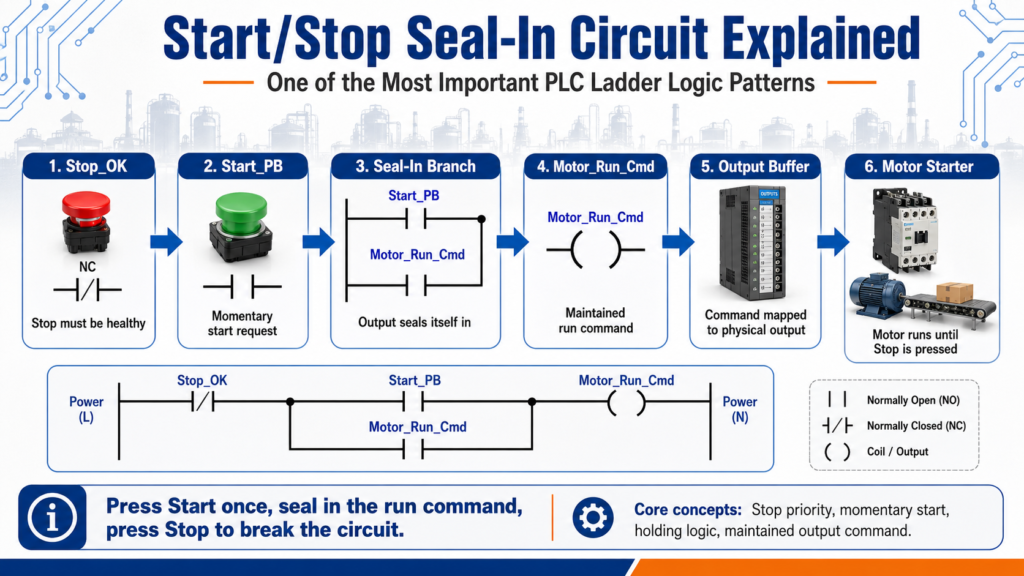
One of the first ladder logic circuits every PLC beginner should understand is the Start/Stop seal-in circuit.
This circuit is also called a:
Start/Stop circuit
Seal-in circuit
Holding circuit
Motor starter logic
Three-wire control circuit
Even though it looks simple, this pattern is extremely important because it teaches several core PLC concepts:
Normally closed stop logic
Normally open start logic
Seal-in / holding logic
Output command memory
Safe stop priority
Basic motor control structure
Standard stop/start control as a programming objective and also explains that a seal-in contact is used to keep a coil energized after the Start button is released.
1. What Is a Seal-In Circuit?
A seal-in circuit allows an output to stay ON after a momentary Start push button is released.
In simple words:
Press Start once, and the motor keeps running until Stop is pressed.
Without a seal-in branch, the output would only stay energized while the Start button is physically held down.
Example:
Operator presses Start
        ↓
Motor output turns ON
        ↓
Seal-in contact closes
        ↓
Operator releases Start
        ↓
Motor stays ON
If the seal-in contact does not close, the coil energizes only while the Start button is pressed; when the button is released, the coil de-energizes.
2. Basic Control Philosophy
The basic philosophy is:
Stop must be healthy
Start creates the run request
Output seals itself in
Stop breaks the circuit
A simple logical expression looks like this:
Stop_OK AND (Start_PB OR Motor_Run_Output) = Motor_Run_OutputIn plain English:
If Stop is OK
AND Start is pressed
OR the motor is already running
THEN keep the motor running
This is the heart of a basic seal-in circuit.
3. Why the Stop Contact Comes First
In a standard Start/Stop rung, the Stop condition is usually placed first in series with the rest of the logic.
Conceptually:
Stop_OK → Start / Seal-In Branch → Motor OutputThat means Stop has priority.
If Stop is pressed, the circuit opens and the output drops out.
This is important because Stop should interrupt the run command regardless of whether Start is pressed or the seal-in branch is active.
Devices intended to perform a stop function are normally wired in series, while start devices are normally wired in parallel.
That same idea carries into ladder logic:
Stop conditions = series path
Start / hold-in conditions = parallel path
4. Basic Ladder Logic Concept
A classic PLC seal-in rung can be represented like this:
|----[ Stop_OK ]----+----[ Start_PB ]----------------( Motor_Run )----|
|                   |                                                 |
|                   +----[ Motor_Run ]--------------------------------|
How it works:
- Stop_OK must be true.
- Pressing Start_PB energizes Motor_Run.
- Once Motor_Run turns on, its own contact closes in the parallel branch.
- The operator can release Start_PB.
- Motor_Run stays on through the seal-in branch.
- Pressing Stop makes Stop_OK false and drops the output.
This is a simple but powerful control pattern.
5. Step-by-Step Operation
Step 1: Machine stopped
Stop_OK = TRUE
Start_PB = FALSE
Motor_Run = FALSE
The motor is off because Start has not been pressed.
Step 2: Operator presses Start
Stop_OK = TRUE
Start_PB = TRUE
Motor_Run = TRUE
The rung becomes true and the output energizes.
Step 3: Seal-in contact closes
Motor_Run = TRUEThe Motor_Run contact in the parallel branch becomes true.
This creates the holding path.
Step 4: Operator releases Start
Start_PB = FALSE
Motor_Run = TRUE
The motor stays running because the seal-in branch is now true.
Step 5: Operator presses Stop
Stop_OK = FALSE
Motor_Run = FALSE
The Stop condition breaks the rung and the motor turns off.
6. Why Start Is Usually Momentary
The Start button is normally a momentary normally open push button.
That means:
Not pressed = open / false
Pressed = closed / true
Released = open / false again
The Start button does not need to stay pressed because the seal-in branch keeps the output energized after the initial command.
This is why a Start button is a request, not the final run condition.
A better way to think about it:
Start_PB = operator request
Motor_Run = maintained command
7. Why Stop Is Usually Normally Closed
A Stop push button is commonly wired as a normally closed device.
That means:
Healthy / not pressed = closed / true
Pressed = open / false
Broken wire = open / false
This is useful because if the stop circuit wire breaks, the PLC or control circuit sees the stop condition as not healthy.
Simple concept:
Stop_OK = TRUE  → machine may run
Stop_OK = FALSE → machine must stop
For real machines, remember that a normal Stop is different from an Emergency Stop. A normal Stop can be part of PLC logic. An E-Stop should be handled through a proper safety circuit, as discussed in the previous post.
8. Seal-In vs Latch / Unlatch
A seal-in circuit is not the same as using latch/unlatch instructions.
Seal-in logic
Uses normal output coil
Output stays on only while rung logic remains true
Stop condition breaks the rung
Power cycle usually clears the output
Latch / Unlatch logic
Uses retentive instructions
Latched bit may stay on until explicitly unlatched
Can remain true even after logic changes
Needs careful reset logic
Stop/Start logic using OTL and OTU, then moves into standard Stop/Start control using a seal-in style method. It asks learners to consider what happens if power is lost in the stop switch circuit, which is a key safety and control-design question.
For beginners, a seal-in circuit is usually easier and safer to understand than latch/unlatch instructions.
9. Industrial Version With Permissives
A real industrial motor rung usually has more conditions than just Start and Stop.
Example:
Stop_OK
AND Safety_OK
AND Motor_Overload_OK
AND Auto_Mode
AND No_Faults
AND (Start_PB OR Motor_Run)
THEN Motor_Run
In ladder-style logic:
|--[Stop_OK]--[Safety_OK]--[OL_OK]--[No_Faults]--+--[Start_PB]----(Motor_Run)--|
|                                                |                              |
|                                                +--[Motor_Run]----------------|
This is much closer to real plant logic.
The Start button does not directly run the motor. It only starts the command if all permissives are healthy.
10. Recommended Tag Names
For a modern tag-based PLC system, better tag names make the logic easier to understand.
Input tags
DI_Start_PB
DI_Stop_OK
DI_Safety_OK
DI_Motor_OL_OK
DI_Motor_FB
Internal command tags
Motor_Run_Request
Motor_Run_Cmd
Motor_Seal_In
Motor_Start_Permissive
Output tags
DO_Motor_Starter
DO_Run_Light
DO_Fault_Light
Fault / status tags
Motor_Overload_Fault
Motor_Feedback_Fault
Motor_Running
Motor_Available
This naming style makes the program more readable and easier to troubleshoot.
11. Request vs Command vs Output
A professional way to think about motor control is:
Request → Command → OutputExample:
Start_PB = request from operator
Motor_Run_Cmd = PLC decision
DO_Motor_Starter = physical output
This separation is important.
A beginner may write:
Start_PB = Motor_OutputBut a better industrial approach is:
Start_PB creates a request
PLC checks permissives and faults
PLC creates a run command
Output buffer energizes the physical output
This helps when you later add:
Auto mode
Manual mode
Faults
Alarms
Motor feedback
HMI commands
Safety status
12. Troubleshooting a Start/Stop Seal-In Circuit
When a motor does not stay running, ask:
| Question | What It Means |
|---|---|
| Does Start_PB turn on? | PLC sees the start request |
| Is Stop_OK true? | Stop circuit is healthy |
| Are all permissives true? | Safety, overload, faults, mode are okay |
| Does Motor_Run turn on briefly? | Start works, but seal-in may be missing |
| Does Motor_Run drop when Start is released? | Seal-in contact may not be closing |
| Is the same bit used for the seal-in contact? | Wrong address/tag can break the hold |
| Is another rung turning the bit off? | Output conflict or reset logic |
| Is the output mapped correctly? | Command may not reach the physical output |
A common beginner issue is using the wrong bit in the seal-in branch.
Example mistake:
Start_PB seals in Start_PBBetter:
Motor_Run seals in Motor_RunThe seal-in branch should usually use the output command or internal run bit that you want to maintain.
13. Common Beginner Mistakes
Mistake 1: No seal-in branch
The motor only runs while Start is held.
Mistake 2: Stop placed only on one branch
Stop must interrupt both the Start and seal-in path.
Mistake 3: Using latch/unlatch too early
Latch instructions can work, but they require careful reset and fault logic.
Mistake 4: Using the physical output everywhere
Better practice is often to use an internal command bit, then map it to the physical output in an output buffer.
Mistake 5: Ignoring overload or safety permissives
A motor should not run just because Start was pressed.
Mistake 6: Duplicate output coils
Using the same output coil in multiple rungs can cause unexpected behavior.
14. Basic Example for Beginners
Here is a simple beginner version:
Rung 1 - Motor Run Command

Stop_OK     Start_PB
--] [----------] [--------------------( Motor_Run_Cmd )
        |                         |
        | Motor_Run_Cmd           |
        +----] [------------------+
Explanation
Stop_OK must be true.
Start_PB energizes Motor_Run_Cmd.
Motor_Run_Cmd seals itself in.
Pressing Stop breaks the rung.
15. More Industrial Version
Here is a more realistic version:
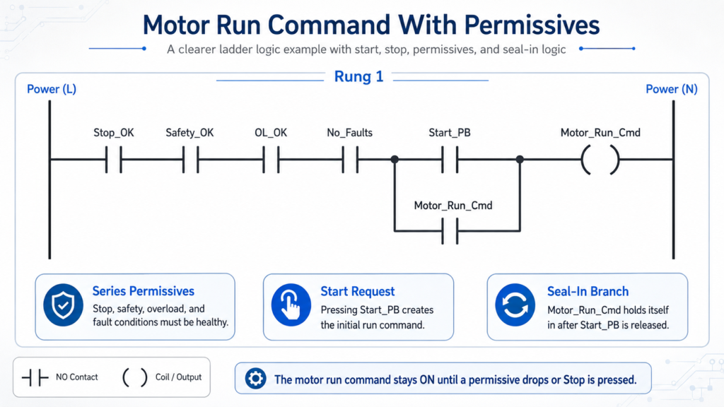
Explanation
The motor can only run if Stop, Safety, Overload, and Fault conditions are healthy.
Start creates the initial command.
The command seals itself in.
Any unhealthy permissive drops the command.
16. Output Mapping
A clean program often separates command logic from physical outputs.
Example:
Rung 1:
Motor_Run_Cmd = logic decision

Rung 2:
Motor_Run_Cmd → DO_Motor_Starter
This keeps the program cleaner.
Motor_Run_Cmd = internal PLC decision
DO_Motor_Starter = actual output to the field device
This structure becomes very helpful as programs get larger.
Final Thoughts
The Start/Stop seal-in circuit is one of the most important ladder logic patterns for beginners.
It teaches:
Momentary input control
Maintained output commands
Stop priority
Seal-in / holding logic
Series and parallel logic
Basic motor control
Troubleshooting discipline
The key idea is simple:
Press Start once.
The output seals itself in.
Press Stop to break the command.
In real industrial control, the same concept becomes more professional when we add:
Safety_OK
Overload_OK
No_Faults
Mode selection
Motor feedback
HMI commands
Output buffering
Once you understand the seal-in circuit, many other PLC patterns become easier to understand.