Sensor Debounce in Industrial Control Systems
Filtering Noisy Inputs and Preventing Unstable PLC Logic
In industrial automation, field devices do not always send perfectly clean signals to the PLC. A sensor, limit switch, push button, or relay contact may rapidly turn ON and OFF for a short period of time, even though the real-world condition has not actually changed.
This rapid unintended switching is commonly known as noise, chatter, or contact bounce.
Sensor debounce is a control strategy used to filter these rapid ON/OFF transitions before the signal is accepted as valid by the PLC program.
Without debounce logic, the PLC may interpret these false transitions as real events. This can lead to:
- False triggers
- Incorrect counts
- Unstable machine behavior
- Intermittent faults
- Outputs turning ON and OFF unexpectedly
Debounce is a simple concept, but it is very important for building reliable and maintainable PLC programs.
What Causes Signal Chatter?
Signal chatter can be caused by several real-world conditions, including:
- Mechanical vibration
- Electrical noise
- Loose wiring
- Contact bounce from push buttons or relays
- Sensors detecting unstable targets
- Photoeyes seeing product edges, gaps, or reflections
In a real production environment, these conditions can happen often. This is why raw input signals should not always be trusted immediately.
Where Should Debounce Be Used?
Debounce is primarily used on PLC inputs.
Common devices that may require debounce include:
- Photoelectric sensors
- Proximity sensors
- Limit switches
- Push buttons
- Pressure switches
- Flow switches
- Mechanical contacts
- Relay feedback contacts
A good programming practice is:
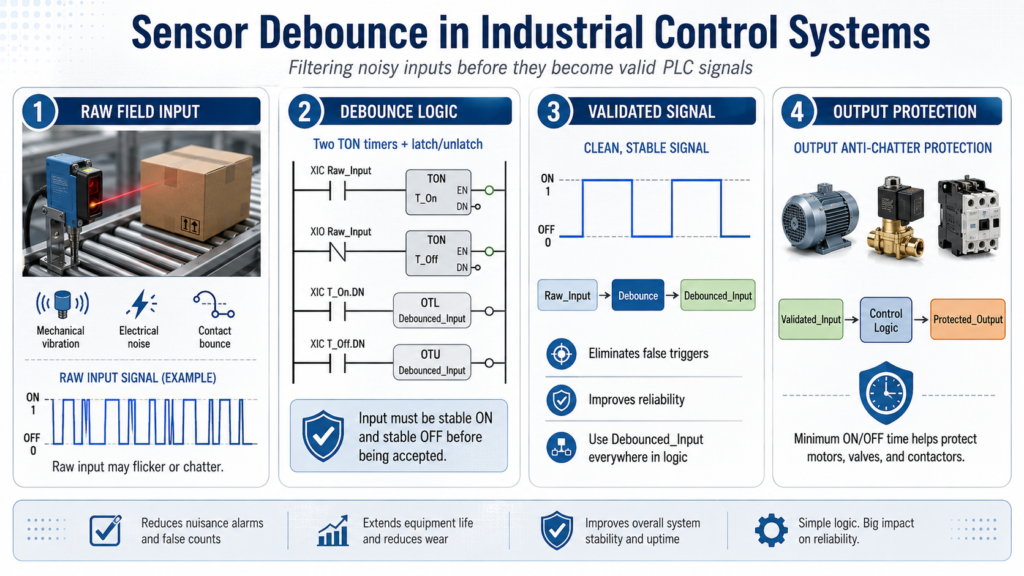
Raw Input → Debounce Logic → Validated Input → Control LogicAvoid using raw field inputs directly throughout your PLC program.
Instead, bring the raw input into an input conditioning routine, debounce it if needed, and then use the validated signal everywhere else in the program.
Recommended Design Concept
A clean PLC structure separates the raw field signal from the validated logic signal.
Example:
PE1_Raw → PE1_DBWhere:
PE1_Rawis the actual raw input from the field device.PE1_DBis the debounced input used by the PLC logic.
This makes the program easier to troubleshoot because you can compare the real input against the cleaned signal.
Input Debounce Template
Industrial Standard Using Two TON Timers
One clear and reliable debounce method uses two TON timers:
- One timer validates the ON condition.
- One timer validates the OFF condition.
This method is easy to understand, easy to troubleshoot, and works well for training and real industrial applications.
Rung 1 — ON Debounce Timer
XIC Raw_Input TON T_Input_OnPurpose:
The raw input must remain ON for a defined amount of time before the PLC accepts it as a valid ON signal.
Example preset:
100 msRung 2 — OFF Debounce Timer
XIO Raw_Input TON T_Input_OffPurpose:
The raw input must remain OFF for a defined amount of time before the PLC accepts it as a valid OFF signal.
Example preset:
100 msRung 3 — Latch the Debounced Input
XIC T_Input_On.DN OTL Debounced_InputPurpose:
When the ON debounce timer is done, the input is considered stable ON. The debounced input is latched ON.
Rung 4 — Unlatch the Debounced Input
XIC T_Input_Off.DN OTU Debounced_InputPurpose:
When the OFF debounce timer is done, the input is considered stable OFF. The debounced input is unlatched.
Result of the Debounce Logic
With this logic:
- The input must be stable ON before the PLC turns the debounced bit ON.
- The input must be stable OFF before the PLC turns the debounced bit OFF.
- Short noise pulses are ignored.
- The control logic receives a cleaner and more reliable signal.
After debounce, use the debounced tag everywhere in the program:
Use:     Debounced_Input
Avoid:   Raw_Input
This keeps the rest of the PLC program clean, stable, and easier to troubleshoot.
Important Note: TON vs TOF
Debounce can also be created using a combination of TON and TOF timers.
However, in many industrial PLC training and troubleshooting situations, using two TON timers is often clearer and more predictable.
The two-TON method clearly separates:
- ON validation
- OFF validation
This makes the logic easier to explain, test, and troubleshoot.
What About Outputs?
Technically, outputs do not need debounce because outputs are controlled by the PLC program, not by noisy field signals.
However, outputs can still rapidly turn ON and OFF if the internal logic driving them is unstable.
In this case, the correct term is not debounce.
The better term is:
Anti-Chatter Protectionor
Minimum ON/OFF Time ProtectionOutput Anti-Chatter Protection
Output anti-chatter logic is used to prevent equipment from cycling too quickly.
This is especially important for devices such as:
- Motors
- Pumps
- Contactors
- Solenoid valves
- Compressors
- Hydraulic valves
Rapid cycling can cause unnecessary wear, overheating, nuisance faults, or mechanical damage.
Output Protection Template
A simple output protection method is to require a command to remain true for a minimum amount of time before energizing the output.
Minimum ON Time Example
XIC Command        TON T_MinOn
XIC T_MinOn.DN     OTE Output
Purpose:
The command must remain ON long enough before the physical output is energized.
This helps prevent short unstable command pulses from turning the output ON.
Optional Minimum OFF Time
XIO Command TON T_MinOffPurpose:
The output or command must remain OFF for a minimum amount of time before being allowed to restart.
This is useful for equipment that should not restart immediately after stopping.
Correct Control Flow
A professional PLC program should follow this type of structure:
Raw Input
   ↓
Input Conditioning / Debounce
   ↓
Validated Input
   ↓
Control Logic
   ↓
Output Protection
   ↓
Physical Output
A poor design would be:
Raw Input → OutputThat approach may work in a simple simulation, but it is not a good standard for real industrial machines.
Recommended Naming Convention
| Signal Type | Example |
|---|---|
| Raw Input | PE1_Raw |
| Debounced Input | PE1_DB |
| Command | Cmd_Valve |
| Physical Output | DO_Valve |
| ON Debounce Timer | T_PE1_On |
| OFF Debounce Timer | T_PE1_Off |
| Minimum ON Timer | T_Valve_MinOn |
| Minimum OFF Timer | T_Valve_MinOff |
Good tag naming makes troubleshooting easier because the purpose of each signal is clear.
Common Mistakes to Avoid
Here are some common mistakes when dealing with noisy signals and unstable outputs:
1. Using Raw Inputs Directly
Avoid using raw field inputs throughout the PLC program.
Instead, use:
Raw_Input → Debounced_InputThen use the debounced input in your machine logic.
2. Using Only ON Delay
Some programs only validate the ON condition but ignore the OFF condition.
This can still allow unstable OFF transitions to affect the process.
A more complete debounce strategy validates both:
- Stable ON
- Stable OFF
3. Using Too Much Debounce Time
Debounce time should be long enough to filter noise, but not so long that it makes the machine respond slowly.
Typical debounce values may be:
50 ms to 250 msThe correct value depends on the device, machine speed, and process requirements.
4. Calling Output Protection “Debounce”
Inputs are debounced.
Outputs are protected from chatter.
This distinction is important because it helps technicians and programmers understand the real purpose of the logic.
Real Industrial Programming Practice
In more advanced PLC systems, debounce logic is often built into reusable structures such as:
- AOIs in Studio 5000
- Function blocks
- Standard input conditioning routines
- Device control templates
This helps keep the programming consistent across machines, lines, and plant areas.
Instead of writing different debounce logic for every sensor, a standard reusable block can be applied to many input devices.
This improves:
- Consistency
- Troubleshooting
- Program readability
- Maintenance
- Long-term reliability
Practical Example
A photoelectric sensor is used to detect boxes on a conveyor.
Without debounce, vibration, reflections, or product edges may cause the signal to flicker rapidly.
The PLC may see multiple box detections when only one box is actually present.
With debounce, the sensor must remain ON for a short time before the PLC accepts the box as detected.
The logic changes from this:
Photoeye flickers → PLC counts multiple boxesTo this:
Photoeye stable ON → PLC counts one valid boxThis small improvement can prevent false counts, bad sequencing, and unnecessary troubleshooting.
Final Thoughts
Sensor debounce is a basic but powerful technique in industrial control systems.
Use debounce on inputs to clean noisy or unstable field signals.
Use anti-chatter protection on outputs to prevent equipment from rapidly cycling.
A good design follows this structure:
Raw_Input → Debounced_Input → Control_Logic → Protected_OutputThis approach helps create PLC programs that are more reliable, easier to troubleshoot, and closer to real industrial programming standards.
For technicians learning PLC logic, debounce is an important step toward understanding how real machines are made stable, safe, and maintainable.
Technician Takeaway:
Do not trust every raw input immediately. In real machines, sensors and contacts can chatter due to vibration, noise, or mechanical bounce. Debounce logic helps the PLC confirm that a signal is stable before using it in the control logic. For outputs, use anti-chatter or minimum ON/OFF protection to prevent rapid cycling and protect equipment.