20. VFD Parameters Every Technician Should Understand (20 of 22)
Motor Data, Start Source, Speed Reference, Ramps, Protection, and Troubleshooting
Introduction
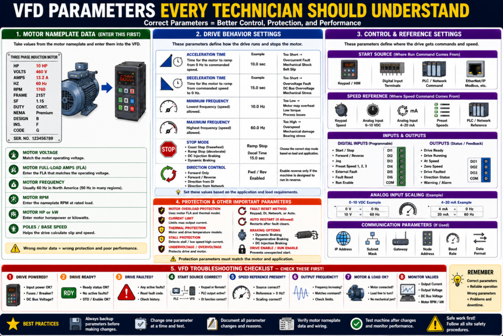
A VFD, or Variable Frequency Drive, can do much more than simply start and stop a motor. A VFD controls how the motor starts, how fast it runs, how it stops, where the command comes from, where the speed reference comes from, and how the motor is protected.
That control is done through parameters.
A simple way to understand it is:
VFD parameters are the settings that tell the drive how to control and protect the motor.
When replacing, troubleshooting, or commissioning a VFD, understanding the main parameters is critical. A drive may be powered up and healthy, but if the start source, speed reference, motor data, or protection settings are wrong, the motor may not run correctly.
The motor control textbook explains that motor specifications are programmed into the VFD to ensure optimum drive performance and adequate fault and overload protection.
What Are VFD Parameters?
VFD parameters are programmable settings inside the drive.
They define things like:
Motor voltage
Motor full-load amps
Motor frequency
Motor RPM
Acceleration time
Deceleration time
Start source
Speed reference source
Minimum speed
Maximum speed
Stop mode
Direction control
Fault reset method
Digital input functions
Analog input scaling
Motor overload protection
Communication settings
A VFD is not a “one setting fits all” device. The same drive model can behave very differently depending on how it is programmed.
1. Motor Nameplate Parameters
The first group of parameters comes from the motor nameplate.
These are some of the most important settings in the drive.
Common motor nameplate parameters include:
Motor Voltage
Motor Full-Load Amps
Motor Frequency
Motor RPM
Motor Horsepower or kW
Motor Poles or Base Speed
Nameplate frequency as one of the values programmed into the VFD, and the VFD chapter shows that nameplate data is used for drive setup and motor protection.
Why Motor Data Matters
The VFD uses motor data to calculate and control:
- Motor overload protection
- Torque behavior
- Slip compensation
- Speed display
- Current limits
- Autotune behavior
- Drive protection logic
- Performance under load
Practical rule:
Before entering VFD parameters, take a clear picture of the motor nameplate.
2. Motor Voltage
The motor voltage parameter must match the motor nameplate and the actual motor connection.
Example:
Motor Nameplate: 230/460 V
Plant Supply: 460 V
Motor Voltage Parameter: 460 V
If the motor voltage is entered incorrectly, the motor may run poorly or the drive may not protect it correctly.
Common symptoms of wrong motor voltage setting:
- Poor torque
- Motor heating
- Overcurrent trips
- Incorrect V/Hz ratio
- Drive fault
- Poor acceleration
3. Motor Full-Load Amps
Motor full-load amps, or FLA, is one of the most critical parameters.
Example:
Motor Nameplate:
230/460 V
13.2/6.6 A

If operating at 460 V:
Use 6.6 A
The motor glossary defines full-load current as the current required for the motor to produce full-load torque at rated speed.
The drive uses this value for motor thermal protection and overload calculations.
Practical warning:
Do not guess motor FLA. Use the nameplate value that matches the actual operating voltage.
4. Motor Frequency
Motor frequency is usually:
60 Hzin the United States, or:
50 Hzin many other regions.
The VFD uses this as the motor’s base frequency.
Example:
Motor Frequency = 60 HzThis means that at 60 Hz, the motor should operate near its rated base speed.
Incorrect frequency settings can affect:
- Speed scaling
- Torque
- Motor heating
- Maximum speed
- V/Hz behavior
5. Motor RPM
The motor RPM parameter is usually entered from the nameplate.
Example:
RPM: 1760This is the rated motor speed at rated load.
The VFD may use RPM for:
- Speed display
- Slip compensation
- Motor model calculations
- Feedback scaling
- Autotune functions
If the RPM is entered wrong, the drive may still run the motor, but displayed speed and motor model behavior may be inaccurate.
6. Acceleration Time
Acceleration time controls how long the motor takes to ramp from zero speed to the commanded speed.
Example:
Acceleration Time = 10 secondsThis means the VFD ramps the motor smoothly instead of applying full speed immediately.
The motor control textbook explains that VFD ramp-up increases voltage and frequency gradually, creating smoother acceleration and reducing stress on the motor and connected load.
If Acceleration Time Is Too Short
Possible problems:
- Overcurrent fault
- Motor overload
- Mechanical shock
- Belt slip
- High torque demand
- Drive trips during start
If Acceleration Time Is Too Long
Possible problems:
- Slow machine response
- Process delay
- Motor may not reach speed quickly enough
- Operator may think the motor is not responding
Practical rule:
Set acceleration based on the load, not just what feels fast.
7. Deceleration Time
Deceleration time controls how long the motor takes to ramp down to stop.
Example:
Deceleration Time = 15 secondsTimed ramp-down allows the drive to bring the motor to a full stop in a preset time and that acceleration and deceleration are separately programmable.
If Deceleration Time Is Too Short
Possible problems:
- Overvoltage fault
- DC bus voltage rises
- Drive trips while stopping
- Mechanical stress
- Product shift
- Belt or gearbox shock
This happens because some loads regenerate energy back into the drive during deceleration. The VFD chapter explains that when the load drives the motor during deceleration, energy can return to the drive and increase DC bus voltage.
If Deceleration Time Is Too Long
Possible problems:
- Machine takes too long to stop
- Process delay
- Safety or sequence timing issues
- Operator frustration
8. Minimum Frequency / Minimum Speed
Minimum frequency defines the lowest speed the motor is allowed to run.
Example:
Minimum Frequency = 10 HzThis prevents the motor from running too slowly.
Why this matters:
- Some motors need minimum speed for cooling.
- Some pumps should not run too slowly.
- Some conveyors may stall at low speed.
- Some processes require minimum flow or motion.
Practical note:
Running a motor too slowly for too long can cause cooling and torque issues, especially if the motor fan depends on shaft speed.
9. Maximum Frequency / Maximum Speed
Maximum frequency defines the highest speed the motor is allowed to run.
Example:
Maximum Frequency = 60 Hzor sometimes:
Maximum Frequency = 75 Hzdepending on the application and approval.
This protects the machine from overspeed.
Important:
Do not increase maximum frequency without understanding motor, load, gearbox, pump, fan, bearing, and process limits.
Overspeed can damage equipment.
10. Start Source
The start source tells the VFD where the Run command comes from.
Common start sources:
Keypad / HIM
Digital input terminals
PLC network command
Serial communication
EtherNet/IP
Remote I/O
If the start source is wrong, the motor may not start even if the PLC or operator is sending a command.
Example problem:
The PLC output is ON, but the VFD is configured for keypad start.
Result: the motor does not start from the PLC.
This is one of the most common VFD troubleshooting issues.
11. Speed Reference Source
The speed reference tells the VFD where the speed command comes from.
Common speed reference sources:
Keypad speed
Analog input 0–10 VDC
Analog input 4–20 mA
Preset speed
PLC network reference
PID controller
If the speed reference is wrong or missing, the drive may receive a Run command but still not run as expected.
Example:
Run Command = ON
Drive Ready = YES
Fault = NO
Speed Reference = 0.0 Hz
Motor does not move
Possible causes:
- Analog signal missing
- PLC reference value is zero
- Wrong reference source
- HMI speed command not entered
- Network reference not mapped
- Minimum speed set too low
12. Stop Mode
The stop mode tells the VFD how to stop the motor.
Common stop modes include:
| Stop Mode | Meaning |
|---|---|
| Coast Stop | Drive removes output and motor coasts |
| Ramp Stop | Drive decelerates motor using decel time |
| DC Injection Braking | Drive injects DC to help stop the motor |
| Dynamic Braking | Drive uses braking resistor to absorb energy |
Braking methods such as dynamic braking, regenerative braking, and DC-injection braking.
Coast Stop
The motor is no longer driven and slows down naturally.
Good for:
- Fans
- Some pumps
- Applications where stopping time is not critical
Ramp Stop
The VFD controls the deceleration.
Good for:
- Conveyors
- Process equipment
- Controlled stopping
Dynamic Braking
A braking resistor absorbs energy from the DC bus.
Good for:
- High inertia loads
- Fast stopping applications
- Loads that regenerate energy during deceleration
13. Direction Control
The direction control parameter determines whether the drive allows forward and/or reverse operation.
Settings may include:
Forward only
Forward and reverse
Reverse disabled
Direction from digital input
Direction from network command
Important:
Only allow reverse if the machine is designed to run reverse.
Wrong reverse operation can damage:
- Pumps
- Fans
- Conveyors
- Gearboxes
- Screw conveyors
- Process equipment
14. Digital Input Functions
VFD digital inputs are programmable.
Common digital input functions include:
Start
Stop
Forward
Reverse
Jog
Preset Speed
External Fault
Fault Reset
Run Enable
Two-wire control
Three-wire control
VFD input examples for two-wire and three-wire control using stop, forward, reverse, and jogging functions, and explains that digital inputs can be programmed for different control methods.
Practical warning:
A wire connected to a digital input does not mean anything until the parameter assigns that input a function.
15. Analog Input Scaling
Analog inputs are commonly used for speed reference.
Common signals:
0–10 VDC
4–20 mA
Analog scaling tells the drive how to interpret the signal.
Example:
4 mA = 0 Hz
20 mA = 60 Hz
or:
0 V = 0 Hz
10 V = 60 Hz
If analog scaling is wrong, the motor speed will be wrong.
Common symptoms:
- Motor runs too slow
- Motor runs too fast
- Speed command does not match HMI
- Motor does not respond to analog signal
- Speed jumps unexpectedly
16. Preset Speeds
Preset speeds are fixed speeds stored in the drive.
Example:
Preset Speed 1 = 20 Hz
Preset Speed 2 = 40 Hz
Preset Speed 3 = 60 Hz
Digital inputs or PLC commands can select which preset speed is active.
Preset speeds are useful when the process only needs a few fixed speeds instead of a continuously variable analog signal.
17. Current Limit
Current limit restricts how much current the drive allows during operation.
If the load demands too much torque, the drive may limit current to protect itself and the motor.
Current limit can help protect equipment, but if set incorrectly, it may prevent the motor from accelerating or carrying the load.
Possible symptoms:
Motor starts but cannot reach speed
Drive limits output
Motor stalls under load
Drive trips on overload
18. Motor Overload Protection
Many VFDs provide motor overload protection based on programmed motor data.
The most drive applications, the drive itself provides overload protection for the motor, based on motor nameplate information programmed into the drive. It also notes that external overload relays may be required if the VFD is not approved for overload protection or if multiple motors are fed from one drive.
Important:
The drive can only protect the motor properly if the motor data is entered correctly.
19. Fault Reset Method
Fault reset parameters define how faults can be cleared.
Common reset methods:
Keypad reset
Digital input reset
PLC network reset
Power cycle
Auto restart / auto reset, if allowed
Be careful with automatic reset.
Auto reset can be useful in some process systems, but it can also create unexpected restart hazards.
Practical rule:
Fault reset should not hide the root cause. Reset only after the condition is corrected and the machine is safe to restart.
20. Communication Parameters
When the VFD communicates with a PLC, communication parameters become critical.
Common communication settings:
IP address
Subnet mask
Gateway
Node address
Baud rate
Device name
Communication format
Data links
Input/output assembly
Network command enable
Network reference enable
If communication parameters are wrong, the PLC may not be able to start the drive, send a speed reference, or read feedback.
21. Local vs Remote Mode
Many drives can operate in local or remote mode.
Local Mode
The drive is controlled from the keypad or HIM.
Start from keypad
Speed from keypad
Stop from keypad
Remote Mode
The drive is controlled by external inputs or PLC.
Start from PLC or terminals
Speed from analog input or network
Stop from PLC or terminals
Common troubleshooting issue:
The PLC is commanding the drive, but the drive is in Local mode.Result:
Drive does not respond to PLC command.22. Monitoring Parameters
VFDs also provide monitoring values, not just setup parameters.
Useful monitored values include:
Output frequency
Output voltage
Output current
Motor RPM
Motor kW
DC bus voltage
Parameter settings
Faults
Real-time VFD data such as frequency output, voltage output, current output, motor RPM, motor kilowatts, DC bus volts, parameter settings, and faults.
These values are very useful during troubleshooting.
Practical VFD Parameter Checklist
Before replacing or commissioning a VFD, record:
Drive manufacturer and model
Drive horsepower / current rating
Input voltage
Output voltage
Motor voltage
Motor FLA
Motor frequency
Motor RPM
Motor HP / kW
Start source
Speed reference source
Minimum frequency
Maximum frequency
Acceleration time
Deceleration time
Stop mode
Direction settings
Digital input assignments
Analog input type and scaling
Fault reset method
Communication settings
VFD fault history
Backup file available?
Common Parameter Problems
| Symptom | Possible Parameter Issue |
|---|---|
| Drive powers up but motor will not run | Wrong start source, fault active, enable missing |
| Motor runs at 0 Hz | Speed reference missing or wrong source |
| Motor runs wrong speed | Analog scaling or max frequency incorrect |
| Motor trips during start | Accel time too short, current limit, motor data wrong |
| Drive faults during stop | Decel time too short, braking setup issue |
| Motor runs backward | Direction setting or output phase sequence |
| PLC cannot control drive | Remote/local mode or network command setting |
| HMI speed does not match drive | Scaling or communication mapping issue |
| Overload trips | Motor FLA wrong, load issue, current limit problem |
VFD Replacement Tip
Before replacing a VFD, always try to obtain:
Parameter backup
Drive fault history
Motor nameplate photo
Wiring photos
Communication settings
I/O terminal assignments
Application notes
HIM/keypad settings
Practical rule:
A replacement VFD without the correct parameters is only a powered box. The machine needs the correct configuration to operate.
Troubleshooting with Parameters
When troubleshooting a VFD, check these first:
1. Is the drive faulted?
2. Is the drive ready?
3. Is the drive in Local or Remote?
4. What is the start source?
5. What is the speed reference source?
6. Is the speed reference greater than zero?
7. Are motor nameplate parameters correct?
8. Are acceleration/deceleration times reasonable?
9. Are digital inputs assigned correctly?
10. Are communication settings correct?
This avoids wasting time replacing hardware when the issue is configuration.
Industrial Pro Tips
Pro Tip 1 — Always Back Up Parameters
Before making changes, back up the existing configuration if possible.
Pro Tip 2 — Change One Parameter at a Time
Do not change many settings at once unless you have a documented plan.
Pro Tip 3 — Record Before and After Values
Document what was changed and why.
Pro Tip 4 — Verify Motor Nameplate Data
Wrong motor data creates wrong protection and poor performance.
Pro Tip 5 — Check Start Source and Speed Reference First
Many “drive will not run” problems are caused by these two settings.
Quick Summary
VFD parameters define how the drive controls and protects the motor.

Motor nameplate data is critical.

Motor FLA affects overload protection.

Acceleration time controls ramp-up.

Deceleration time controls ramp-down.

Start source tells the drive where Run comes from.

Speed reference tells the drive where speed comes from.

Stop mode controls how the motor stops.

Digital inputs must be assigned by parameter.

Analog inputs must be scaled correctly.

Communication settings must match the PLC/network.

A VFD needs correct parameters to behave correctly.
Final Thoughts
VFD parameters are the key to how a drive behaves. A VFD may have power, no visible fault, and a good motor connected, but if the parameters are wrong, the machine may not run correctly.
For automation technicians, the most important parameters to understand are motor nameplate data, start source, speed reference, acceleration time, deceleration time, stop mode, digital inputs, analog scaling, overload protection, and communication settings.
When troubleshooting a VFD, do not only look at the Run command. Check the parameter setup that defines where the command comes from, where the speed comes from, how the motor ramps, and how the drive protects the motor.
A good technician does not guess VFD settings. A good technician reads the nameplate, checks the parameters, backs up the configuration, documents changes, and verifies machine behavior after the change.