19. VFD Basics for Industrial Motor Control (19 of 22)
Understanding Variable Frequency Drives in Industrial Motor Control
Introduction
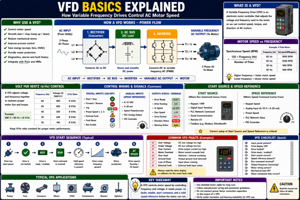
A VFD, or Variable Frequency Drive, is one of the most important devices used in modern industrial motor control. VFDs are used to control the speed, torque, acceleration, deceleration, and direction of AC motors.
In a traditional across-the-line motor starter, the motor receives full voltage and fixed frequency as soon as the contactor closes. With a VFD, the motor does not simply receive fixed power. Instead, the drive electronically controls the voltage and frequency supplied to the motor.
A simple way to understand it is:
A VFD controls motor speed by controlling the frequency sent to the motor.
This is important because AC induction motor speed depends on frequency and the number of motor poles. A VFD makes it practical to vary frequency, which allows the motor speed to be controlled instead of being fixed at one speed.
What Is a VFD?
A Variable Frequency Drive is an electronic motor controller used mainly with AC induction motors.
A VFD system usually includes:
AC motor
VFD controller
Operator interface / HIM / keypad
PLC or external control signals, depending on the system
VFD systems identifies the motor, drive, operator interface, and PLC as common parts of a VFD system, and notes that three-phase induction motors are generally used with VFDs.
A VFD can control:
- Motor speed
- Motor direction
- Acceleration time
- Deceleration time
- Torque behavior
- Current limit
- Start/stop method
- Speed reference source
- Fault handling
- Communication with PLC
Why VFDs Are Used
VFDs are used because they provide better control than a basic contactor starter.
Common reasons to use a VFD include:
- Control motor speed
- Reduce mechanical shock during startup
- Reduce stress during stopping
- Improve process control
- Save energy on pumps and fans
- Provide motor protection
- Allow controlled acceleration and deceleration
- Provide diagnostics and fault history
- Integrate with PLCs and HMIs
- Change direction electronically when designed for it
Adjustable-speed drives allow motor-driven loads to operate over a wide speed range, and matching motor speed to load requirements can improve motor installation efficiency and performance.
Across-the-Line Starter vs VFD
A basic motor starter and a VFD both can start a motor, but they do it very differently.
| Feature | Across-the-Line Starter | VFD |
|---|---|---|
| Motor speed | Fixed by line frequency | Adjustable |
| Starting method | Full voltage immediately | Controlled ramp-up |
| Stopping method | Coast or hard stop depending circuit | Controlled ramp-down |
| Direction | Requires reversing starter | Can be controlled by drive logic if configured |
| Diagnostics | Limited | Faults, status, current, speed, alarms |
| Control inputs | Start/Stop circuit | Digital, analog, network, keypad |
| Speed control | Not available | Main purpose |
With an across-the-line starter:
Line voltage + fixed frequency → motor runs at near rated speedWith a VFD:
Variable voltage + variable frequency → motor speed is controlledThe textbook explains that an AC motor drive delivers varying voltage and frequency to the motor, and that the higher the frequency supplied to the motor, the faster it runs.
How a VFD Works
A VFD has three major internal sections:
Converter / Rectifier
DC Bus / DC Link
Inverter
The motor control textbook describes the major sections as: a converter that rectifies incoming AC into DC, a DC bus/DC link that provides smooth rectified DC voltage, and an inverter that switches DC rapidly to create a simulated AC output to the motor.
1. Converter / Rectifier
The converter, also called the rectifier section, takes incoming AC power and converts it to DC.
Example:
AC input power → Rectifier → DC powerThis is the first stage inside the drive.
The adjustable-speed drive chapter describes the converter as a full-wave rectifier that converts applied AC power to DC.
2. DC Bus / DC Link
The DC bus, also called the DC link, stores and smooths the DC power.
It usually includes components such as capacitors and sometimes inductors.
Simple concept:
Rectified DC → DC Bus → stable DC source for inverterThe DC bus connects the rectifier output to the inverter input.
3. Inverter
The inverter takes the DC bus voltage and switches it rapidly to create a controlled AC output.
This output is not a perfect sine wave like utility power. It is a pulse-width modulated output that the motor responds to like AC power.
The textbook explains that PWM uses inverter switches to divide the simulated sine-wave output into narrow voltage pulses and modulate their width.
Basic VFD flow:
AC Input → Rectifier → DC Bus → Inverter → Variable AC Output → MotorFrequency Controls Speed
The main reason a VFD controls speed is because AC motor speed is tied to frequency.
The basic motor speed formula is:
Synchronous Speed = (120 × Frequency) / Number of PolesExample:
4-pole motor at 60 Hz ≈ 1800 RPM synchronous speed
4-pole motor at 30 Hz ≈ 900 RPM synchronous speed
The VFD training material uses the same relationship for VFD speed calculations: RPM = (120 × f) ÷ p.
So when the VFD lowers frequency, motor speed decreases. When the VFD increases frequency, motor speed increases.
Volts per Hertz Concept
A VFD normally changes voltage along with frequency.
This is called V/Hz control, or volts-per-hertz control.
Simple idea:
Lower frequency → lower voltage
Higher frequency → higher voltage
Why?
Because the motor needs a proper balance of voltage and frequency to maintain good magnetic flux and torque behavior.
The volts-per-hertz ratio is generally regulated to a constant value, using 480 V / 60 Hz = 8 V/Hz as an example.
Example:
480 V / 60 Hz = 8 V/Hz

At 30 Hz:
30 × 8 = 240 V approximately
This is a simplified concept, but it helps explain why a VFD controls both voltage and frequency.
VFD Power Wiring
Typical VFD power wiring has two sides.
Line Side
The line side is the input power to the VFD.
Common terminals:
L1, L2, L3or for some drives:
L/L1, N/L2depending on single-phase or three-phase input.
Load Side / Motor Side
The motor side is the VFD output to the motor.
Common terminals:
T1, T2, T3or:
U, V, WVFD power wiring includes conductors supplying power to the drive and conductors supplying power from the drive to the motor. North American load conductor designations are commonly T1/T2/T3, while European designations are U/V/W.
Important:
Do not treat a VFD output like a normal contactor output. The drive output is electronically controlled.
VFD Control Wiring
VFDs usually have control terminals for external commands and feedback.
Common control wiring includes:
- Digital inputs
- Digital outputs
- Relay outputs
- Analog inputs
- Analog outputs
- Communication ports
- Safe Torque Off inputs, depending on drive
- External fault inputs
- Speed reference signals
The most VFDs have terminal strips for digital and analog inputs/outputs. Digital signals are ON/OFF, while analog signals vary across a range.
Digital Inputs
Digital inputs are ON/OFF commands.
Examples:
Start / Stop
Forward / Reverse
Jog
Preset Speed 1
Preset Speed 2
External Fault
Fault Reset
Run Enable
VFD digital inputs can be connected to:
- Pushbuttons
- Selector switches
- Relay contacts
- PLC digital output modules
The motor control textbook lists start/stop, forward/reverse, external fault, and preset speed selections as examples of VFD digital input functions.
Analog Inputs
Analog inputs are used for variable speed reference.
Common analog signals:
0–10 VDC
4–20 mA
Examples:
Speed potentiometer
PLC analog output
Pressure controller
Flow controller
Temperature controller
The drive interprets this analog value as a speed command.
Example:
0 V = minimum speed
10 V = maximum speed
or:
4 mA = minimum speed
20 mA = maximum speed
Digital / Relay Outputs
VFD outputs can send status back to the PLC or panel.
Common VFD output signals:
Drive Running
Drive Ready
Drive Faulted
At Speed
Zero Speed
Direction Status
Warning Active
The textbook explains that digital or relay outputs are ON/OFF signals sent by the VFD to devices such as pilot lights, alarms, auxiliary relays, solenoids, and PLC input modules.
Start Source and Speed Reference
Two of the most important VFD setup concepts are:
Start Source
Speed Reference
Start Source
The start source tells the VFD where the Run command comes from.
Examples:
Keypad / HIM
Digital input terminal
PLC network command
Serial communication
EtherNet/IP
Remote I/O
Speed Reference
The speed reference tells the VFD where the speed command comes from.
Examples:
Keypad speed
Analog input 0–10 V
Analog input 4–20 mA
Preset speed
PLC network speed reference
PID controller
This is very important for troubleshooting.
A VFD may not run if the start source is wrong.
A VFD may run at zero speed if the speed reference is missing or set to zero.
Basic VFD Start Sequence
A typical VFD start sequence looks like this:
1. Drive has input power.
2. Drive is not faulted.
3. Drive is enabled / ready.
4. Start command is received.
5. Valid speed reference is present.
6. Drive ramps output frequency upward.
7. Motor accelerates.
8. Drive reports Running or At Speed.
The operator interface allows start/stop and speed adjustment, and can support reversing and switching between automatic external process control and manual speed adjustment.
Acceleration and Deceleration
A major advantage of a VFD is controlled ramping.
Acceleration Time
Acceleration time controls how long the motor takes to ramp from zero speed to the commanded speed.
Example:
0 Hz → 60 Hz in 10 secondsDeceleration Time
Deceleration time controls how long the motor takes to ramp down from commanded speed to stop.
Example:
60 Hz → 0 Hz in 10 secondsVFD material notes that ramp-up and ramp-down are programmable functions, and that controlled deceleration ramps frequency and voltage down until the motor stops.
Why VFDs Save Energy on Pumps and Fans
VFDs are especially useful on centrifugal pumps and fans.
Instead of running a motor at full speed and throttling flow mechanically, the VFD can reduce motor speed to match process demand.
Electronic adjustable-speed drives allow precise control of motor output, and that centrifugal fans and pumps can achieve significant power savings when the motor output is matched to the load.
Examples:
Fan speed reduced when demand is low
Pump speed reduced when pressure is satisfied
Exhaust system slows down during low load
Cooling water pump follows process demand
This can reduce energy use and mechanical wear.
VFDs and Motor Nameplate Data
A VFD must be configured with motor data.
Important motor nameplate values include:
Motor voltage
Motor full-load amps
Motor frequency
Motor RPM
Motor horsepower or kW
Motor overload setting
If these values are wrong, the drive may not protect or control the motor correctly.
Practical rule:
Before setting up a VFD, read the motor nameplate.
Wrong VFD parameters can cause:
- Overload trips
- Poor torque
- Incorrect speed
- Failed autotune
- Drive fault
- Motor overheating
- Poor process control
VFD Command vs Feedback
A VFD system still follows the same industrial philosophy:
Request → Command → Output → FeedbackExample PLC tags:
VFD_Run_Command
VFD_Speed_Reference
VFD_Ready
VFD_Running
VFD_At_Speed
VFD_Faulted
Motor_Run_Feedback
A PLC may command the VFD to run, but the VFD may not run if:
- Drive is faulted
- Drive is not ready
- Start source is wrong
- Speed reference is zero
- Enable input is missing
- Safe Torque Off is active
- Motor overload is active
- Communication fault exists
A good HMI should show both command and feedback:
Run Command: ON
Drive Ready: YES
Drive Running: NO
Drive Fault: ACTIVE
Speed Reference: 45 Hz
Output Frequency: 0 Hz
Common VFD Applications
VFDs are commonly used on:
- Pumps
- Fans
- Conveyors
- Mixers
- Agitators
- Compressors
- Blowers
- HVAC equipment
- Packaging equipment
- Process skids
- Dosing systems
Typical goals:
Control speed
Reduce starting stress
Match process demand
Improve diagnostics
Reduce energy use
Protect the motor
VFD Troubleshooting Basics
When a VFD-controlled motor does not run, check:
1. Is input power present?
2. Is the drive display powered?
3. Is the drive faulted?
4. Is the drive ready?
5. Is Safe Torque Off healthy, if used?
6. Is the start source correct?
7. Is the speed reference present?
8. Is the drive in Local or Remote mode?
9. Are motor parameters correct?
10. Is output frequency increasing?
11. Is motor wiring connected correctly?
12. Is the motor or mechanical load jammed?
A strong troubleshooting phrase:
A VFD needs power, no fault, enable, start command, and speed reference before the motor can run.
Common Beginner Mistakes
Mistake 1 — Only Checking the Run Command
A run command alone is not enough. The drive also needs to be ready, enabled, not faulted, and have a valid speed reference.
Mistake 2 — Ignoring Start Source
The drive may be configured for keypad control while the PLC is trying to start it remotely.
Mistake 3 — Ignoring Speed Reference
The drive may receive a Run command but a speed reference of 0 Hz.
Mistake 4 — Entering Wrong Motor FLA
Wrong motor FLA affects motor overload protection.
Mistake 5 — Treating VFD Output Like Normal AC Power
The VFD output is PWM-controlled power. Troubleshooting and measurement require proper procedures and suitable meters.
Mistake 6 — Replacing a VFD Without Backing Up Parameters
The new VFD may power up, but the machine will not behave correctly if the parameters are not restored.
Practical Field Example
A pump motor is controlled by a VFD.
The HMI shows:
Pump Run Command: ON
Drive Ready: YES
Drive Running: NO
Drive Fault: NO
Speed Reference: 0.0 Hz
In this case, the problem may not be the motor or VFD hardware.
The drive is ready and not faulted, but the speed reference is zero.
Possible causes:
PLC analog output not sending reference
PID output at zero
Speed reference source wrong
Minimum speed set to zero
HMI speed command not entered
Network reference not mapped correctly
This is why a technician must check both:
Run Command
Speed Reference
Quick Summary
VFD = Variable Frequency Drive

Main purpose = control AC motor speed

Basic internal sections = Rectifier, DC Bus, Inverter

Rectifier = converts AC to DC

DC Bus = stores/smooths DC power

Inverter = creates variable-frequency AC output

Frequency controls motor speed

Voltage is adjusted with frequency in V/Hz control

Start Source = where the Run command comes from

Speed Reference = where the speed command comes from

VFDs provide ramp-up, ramp-down, diagnostics, status, and motor protection

A VFD needs power, no fault, enable, start command, and valid speed reference
Final Thoughts
VFDs are one of the most important technologies in industrial motor control. They allow a standard AC induction motor to operate with controlled speed, smooth acceleration, smooth deceleration, direction control, motor protection, and better diagnostics.
For automation technicians, the key is to understand that a VFD is not just an electronic contactor. It is a motor controller.
A contactor applies full voltage and fixed frequency. A VFD builds a controlled output using power electronics.
When troubleshooting a VFD, do not only ask, “Is the run command ON?” Also ask:
Is the drive ready?
Is it faulted?
Is the start source correct?
Is the speed reference valid?
Is the drive output frequency increasing?
Is the motor nameplate data correct?
Is the mechanical load free?
Once you understand these basics, VFD troubleshooting becomes much more logical and much less intimidating.