PLC Inputs, Logic, and Outputs Explained
The Basic Foundation of Every PLC-Controlled System
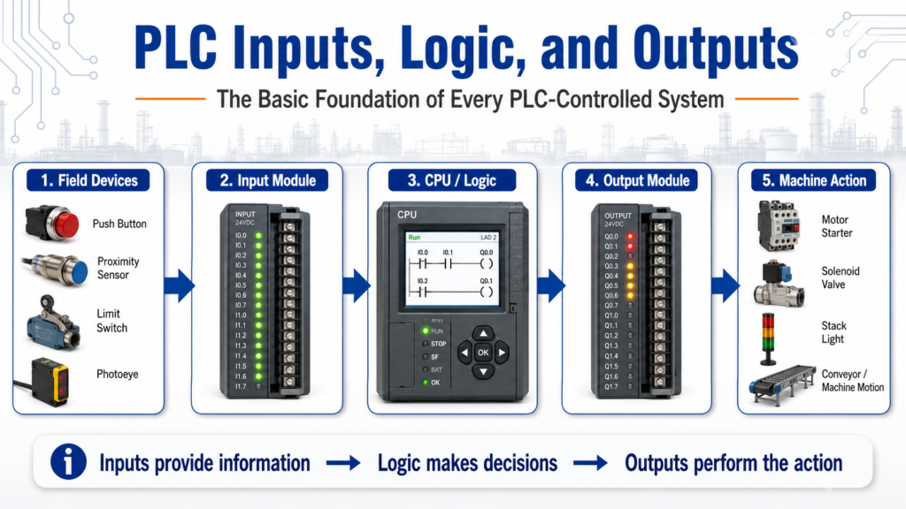
Every PLC-controlled machine, no matter how simple or complex, follows the same basic control idea:
Inputs provide information, logic makes decisions, and outputs perform the action.
This simple concept is the foundation of industrial automation. Whether we are controlling a conveyor, a pump, a door, a valve, a motor starter, or a full production line, the PLC is constantly reading conditions, making decisions, and commanding devices.
The PLCTrainer manual explains that PLC-controlled systems operate through three basic types of devices: inputs, logic, and outputs. Inputs provide information about the process, logic makes decisions based on those inputs, and outputs perform the work or indicate the system condition.
1. What Are PLC Inputs?
PLC inputs are the signals coming from the real world into the controller.
These signals tell the PLC what is happening in the machine or process.
Common input devices include:
| Input Device | What It Tells the PLC |
|---|---|
| Push button | Operator request |
| Selector switch | Mode selection |
| Limit switch | Mechanical position |
| Proximity sensor | Object detected |
| Photoeye | Part present / clear |
| Pressure switch | Pressure reached |
| Level switch | Tank level status |
| Temperature sensor | Process temperature |
| Motor feedback contact | Motor running confirmation |
| Safety relay status | Safety circuit healthy |
In simple words:
Inputs are how the PLC “sees” the machine.
For example, if a proximity sensor detects a box on a conveyor, that sensor sends a signal to the PLC input module. The PLC then uses that information in the ladder logic to decide what should happen next.
The answer key describes “real world” input and output devices as field devices, which is a good industrial term to use when talking about sensors, switches, relays, solenoids, and other devices connected to the PLC.
2. What Is PLC Logic?
PLC logic is the decision-making part of the control system.
The logic is where the program evaluates the inputs and decides which outputs should turn on or off.
A basic logic example could be:
If the Start button is pressed
and the Stop button is healthy
and no fault is active
then turn on the conveyor motor.
In ladder logic, this may look like a simple start/stop circuit. In a more advanced system, the logic may include:
- Interlocks
- Permissives
- Timers
- Counters
- Faults
- Alarms
- Mode selection
- Sequence steps
- Safety status
- Motor feedback
- Analog scaling
- HMI commands
The CPU is the brain of the PLC. The logic is stored there, and the decisions are made there.
That is an important concept:
The PLC does not simply turn outputs on randomly. It follows logic written by the programmer.
3. What Are PLC Outputs?
PLC outputs are the signals leaving the controller to operate real-world devices.
Outputs are how the PLC takes action.
Common output devices include:
| Output Device | What It Does |
|---|---|
| Motor starter | Starts a motor |
| VFD run command | Commands a drive to run |
| Solenoid valve | Opens or closes air/fluid flow |
| Relay | Switches another circuit |
| Stack light | Indicates machine status |
| Alarm horn | Alerts the operator |
| Contactor | Switches power to a load |
| HMI indicator | Displays status to the operator |
In simple words:
Outputs are how the PLC “moves” or “commands” the machine.
I/O section receives inputs from devices like limit switches and proximity sensors, while outputs send signals to devices such as motor starters, relays, and solenoids.
4. The Complete Control Path
A simple PLC control path looks like this:
Field Input Device
        ↓
PLC Input Module
        ↓
PLC Logic / CPU
        ↓
PLC Output Module
        ↓
Field Output Device
        ↓
Machine Action
Example:
Start Push Button
        ↓
PLC Input
        ↓
Start/Stop Logic
        ↓
PLC Output
        ↓
Motor Starter
        ↓
Conveyor Runs
This is the same foundation used in almost every automated system.
5. Simple Example: Conveyor Control
Imagine a conveyor controlled by a PLC.
Inputs
The PLC may receive signals from:
- Start push button
- Stop push button
- Emergency stop circuit status
- Box sensor
- Motor overload contact
- Conveyor running feedback
Logic
The PLC program may check:
- Is Start pressed?
- Is Stop released?
- Is the E-Stop circuit healthy?
- Is there no overload fault?
- Is the conveyor allowed to run?
- Is the correct mode selected?
Outputs
The PLC may command:
- Conveyor motor starter
- Run pilot light
- Fault light
- Alarm message to the HMI
So the control sequence becomes:
Operator presses Start
        ↓
PLC sees Start input
        ↓
PLC checks permissives and faults
        ↓
PLC energizes motor output
        ↓
Motor starter pulls in
        ↓
Conveyor runs
This is why understanding inputs, logic, and outputs is so important.
6. Inputs Do Not Always Mean “Command”
One common beginner mistake is thinking that an input directly controls an output.
For example:
Start button ON = motor ON
In real industrial logic, this is usually not enough.
A better way to think is:
Start button ON = operator request
PLC logic checks conditions
PLC output turns on only if it is safe and allowed
This is where professional PLC programming becomes different from basic wiring.
A real system may require:
Start_PB
AND Stop_OK
AND Safety_OK
AND No_Faults
AND Auto_Mode
AND Motor_Available
THEN Conveyor_Run_Cmd
This approach is much closer to real plant logic because it separates the operator request from the final output command.
7. Inputs, Logic, and Outputs in Troubleshooting
This concept is also powerful for troubleshooting.
When a machine is not working, ask three questions:
1. Does the PLC see the input?
Example:
- The sensor is physically ON.
- But is the PLC input LED ON?
- Is the input bit ON in the software?
2. Is the logic allowing the output?
Example:
- Is there a fault active?
- Is an interlock missing?
- Is the machine in the correct mode?
- Is the sequence in the correct step?
3. Is the output actually operating the device?
Example:
- Is the PLC output ON?
- Is voltage leaving the output module?
- Is the relay or solenoid receiving power?
- Is the field device working?
This troubleshooting method prevents guessing.
Instead of saying, “the PLC is bad,” you can isolate the problem:
Input problem?
Logic problem?
Output problem?
Field device problem?
Wiring problem?
8. Discrete vs Analog Inputs and Outputs
Most beginner PLC examples start with discrete signals.
A discrete signal is simply ON or OFF.
Examples:
Push button pressed = ON
Push button released = OFF

Proximity sensor detects part = ON
No part detected = OFF
But PLCs can also use analog signals, which represent a range of values.
Examples:
| Signal Type | Example |
|---|---|
| Discrete input | Start button ON/OFF |
| Discrete output | Solenoid ON/OFF |
| Analog input | 4–20 mA pressure transmitter |
| Analog output | 0–10 VDC valve position command |
Typical analog inputs can include oven temperature, valve position, and fluid pressure. It also explains that an analog value is continuous rather than discrete.
For beginners, the simple way to remember it is:
Discrete = ON/OFF
Analog = variable value
9. The PLC Is Not the Whole System
Another important lesson is that the PLC is only one part of the control system.
A complete system includes:
- Field devices
- Power supply
- Input modules
- Output modules
- CPU
- Wiring
- Terminal blocks
- Relays
- Contactors
- Motor starters
- VFDs
- HMI
- Safety devices
- Network communication
The PLC as having three main parts: the CPU, the Input/Output section, and the Programming Device. The I/O section communicates information to and from the CPU, while the programming device allows the user to define how the PLC reacts to input information.
This is important because many automation problems are not caused by the PLC program itself. They may be caused by a sensor, cable, fuse, relay, output module, or field device.
10. Practical Technician Mindset
When working with PLC inputs, logic, and outputs, think like this:
For Inputs
Ask:
- What device is sending the signal?
- Is it wired correctly?
- Is the input LED changing?
- Is the PLC address correct?
- Is the signal normally open or normally closed?
- Is the device AC, DC, sinking, or sourcing?
For Logic
Ask:
- What conditions must be true?
- Are there interlocks?
- Are there faults?
- Is the correct mode selected?
- Is there a timer or counter involved?
- Is the sequence waiting for another step?
For Outputs
Ask:
- Is the output bit ON in the PLC?
- Is the output module LED ON?
- Is voltage present at the output terminal?
- Is the relay, solenoid, starter, or drive responding?
- Is the load power available?
This mindset makes troubleshooting cleaner and more professional.
Final Thoughts
The concept of Inputs → Logic → Outputs is one of the most important foundations in PLC programming and industrial automation.
Inputs tell the PLC what is happening.
Logic decides what should happen.
Outputs make something happen.
Once this concept becomes clear, ladder logic becomes easier to understand, troubleshooting becomes more organized, and real industrial systems start to make more sense.
For any beginner learning PLCs, this is one of the first mental models to master:
The machine sends information to the PLC.
The PLC makes a decision.
The PLC commands the machine.
That is the basic cycle behind automated control.