13. Bonus – Electrical Panel Troubleshooting Checklist (13 of 13)
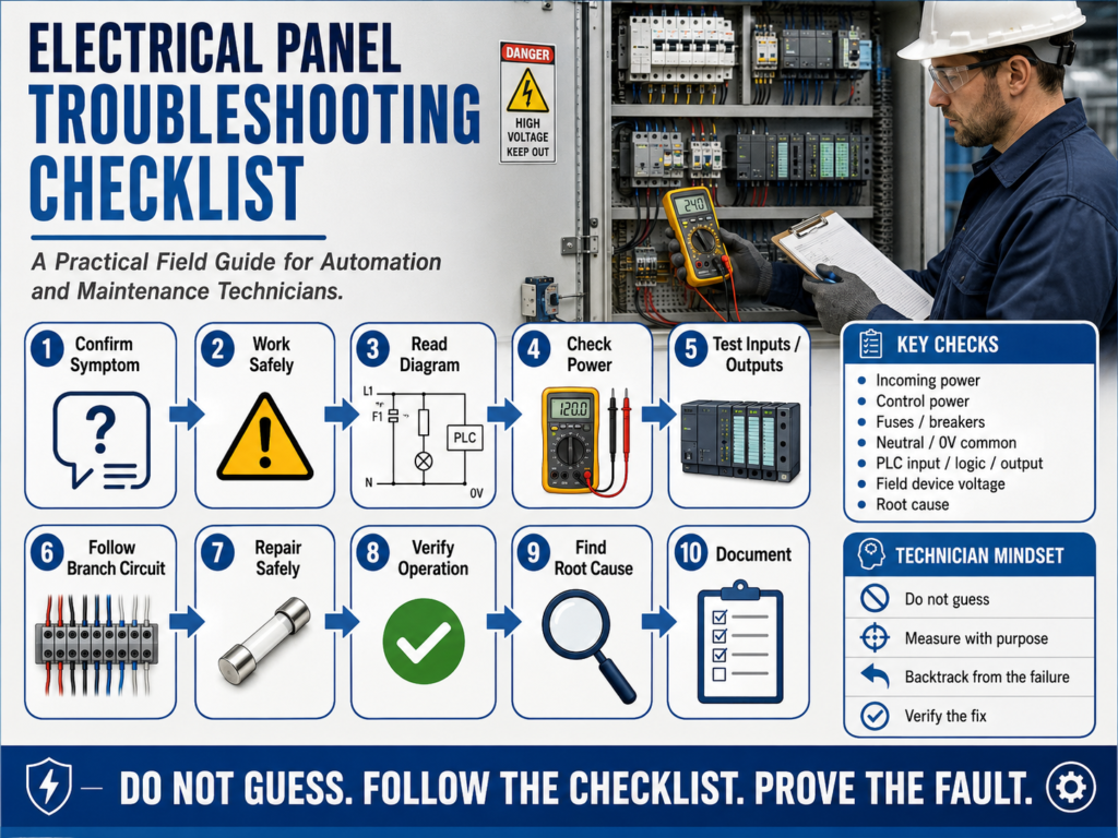
A Practical Field Guide for Automation and Maintenance Technicians
Electrical panel troubleshooting becomes much easier when the technician follows a clear process. The goal is not to guess, replace random parts, or reset faults without understanding the problem.
The goal is to move step by step:
Understand the symptom.
Work safely.
Use the diagram.
Measure with purpose.
Find where the signal or voltage disappears.
Repair safely.
Verify the fix.
Find the root cause.
Document the result.
This checklist brings together the complete troubleshooting mindset from this series.
The TSTrainer Lab Manual emphasizes that a competent technician should use a methodical troubleshooting process and root cause analysis, not random testing or guesswork.
1. Start with the Symptom
Before opening the panel, understand what is actually wrong.
Ask:
What stopped working?
When did it happen?
Is the whole machine down?
Is only one device not working?
Is the HMI showing an alarm?
Did the fault happen during startup, shutdown, or normal operation?
Was there a recent repair, washdown, jam, or adjustment?
A clear symptom gives direction.
| Symptom | First Direction |
|---|---|
| Nothing works | Check source/control power |
| One device does not work | Check that branch circuit |
| PLC input does not turn ON | Check sensor, wiring, input common |
| PLC output LED ON but device OFF | Check output voltage, fuse, wiring, device |
| Motor starter does not pull in | Check control circuit and coil voltage |
| Contactor pulls in but motor does not run | Check power circuit |
2. Safety First
Before testing or touching anything, think safety.
[ ] Identify voltage levels in the panel.
[ ] Wear required PPE.
[ ] Inspect the multimeter and test leads.
[ ] Confirm meter function and range.
[ ] Keep hands and tools clear of exposed energized parts.
[ ] Communicate before energizing or jogging equipment.
[ ] Use Lockout/Tagout before repair or replacement.
[ ] Verify zero energy before touching conductors.
The manual states that once the problem is determined, power feeding the control system should be turned off and a Lock-Out device installed before repair, with the noted exception of resetting thermal overload devices.
3. Use the Electrical Diagram
The diagram is your map.
Before measuring, identify:
Power source
Control voltage
Fuse or breaker
Control devices
PLC input/output points
Relay or contactor coil
Load/device
Neutral or 0V common
Wire numbers
Terminal blocks
The manual explains that the circuit diagram should guide where voltage should be read, what voltage level should be expected, and when voltage should be present.
A good rule:
Diagram = what should happen.
Meter = what is actually happening.
4. Troubleshooting When Nothing Works
When the whole panel or machine appears dead, start with the common source.
[ ] Verify incoming power.
[ ] Check main disconnect.
[ ] Check breakers and fuses.
[ ] Check control transformer primary and secondary.
[ ] Check 24 VDC power supply input and output.
[ ] Check neutral or 0V common.
[ ] Check E-stop and safety relay status.
[ ] Check PLC power and Run/Fault status.
[ ] Check output power/common if PLC outputs are not working.
If everything is down, do not start at one solenoid or one pilot light. Start at the source.
The manual gives this same logic in its “nothing is working” example: the technician begins at the power source, verifies the breaker, and checks voltage at test points.
5. Troubleshooting One Device That Does Not Work
When only one device fails, focus on that branch circuit.
[ ] Confirm only one device is affected.
[ ] Identify the failed device.
[ ] Check the device voltage rating.
[ ] Measure voltage at the device.
[ ] Check both source side and return/common side.
[ ] If voltage is present, inspect the device.
[ ] If voltage is missing, backtrack through the branch.
[ ] Check terminal block, connector, fuse, contact, or PLC output.
[ ] Verify command or logic is active.
Basic branch path:
Source/Fuse → Contact or PLC Output → Terminal Block → Field Wiring → Device → Neutral/0V Common6. PLC Troubleshooting Checklist
For PLC-controlled systems, follow the full signal path.
Field Input → PLC Input → Logic → PLC Output → Field Device → Machine ActionChecklist:
[ ] Check field input device power.
[ ] Check sensor or switch output.
[ ] Check signal at terminal block.
[ ] Check PLC input LED.
[ ] Check input tag/address online.
[ ] Check logic conditions, permissives, interlocks, mode, and faults.
[ ] Check PLC output command.
[ ] Check output LED.
[ ] Measure voltage at PLC output terminal.
[ ] Check output common and fuse.
[ ] Measure voltage at field device.
[ ] Check neutral or 0V return.
[ ] Verify mechanical/pneumatic action.
The manual notes that many PLC system problems are related to the input/output devices and that PLC troubleshooting allows real-time monitoring of the control program.
7. PLC Output LED ON but Device OFF
This is a very common field problem.
Important reminder:
PLC Output LED ON ≠ Field Device EnergizedChecklist:
[ ] Confirm output is ON in logic.
[ ] Confirm output LED is ON.
[ ] Identify output type: relay, sourcing, sinking, transistor, triac.
[ ] Verify output module field power.
[ ] Check output fuse or DC breaker.
[ ] Measure voltage at output terminal.
[ ] Measure voltage at terminal block.
[ ] Measure voltage at field device.
[ ] Check 0VDC common or neutral return.
[ ] Inspect connector and field wiring.
[ ] If voltage is present at the device, check the load or mechanical action.
Common causes:
Missing output common
Blown output fuse
Broken field wire
Loose terminal
Bad connector
Bad solenoid coil
Open neutral
Mechanical valve problem
No air pressure
8. Motor Starter Troubleshooting Checklist
First question:
Does the contactor pull in?If the contactor does not pull in
Troubleshoot the control circuit:
[ ] Verify control voltage.
[ ] Measure voltage across coil A1-A2.
[ ] Check Stop PB circuit.
[ ] Check Start command or PLC output.
[ ] Check safety relay contact.
[ ] Check overload auxiliary contact.
[ ] Check neutral or 0V common.
[ ] Check coil rating and condition.
If the contactor pulls in but the motor does not run
Troubleshoot the power circuit:
[ ] Verify line voltage into contactor.
[ ] Verify load-side voltage leaving contactor.
[ ] Check fuses or breaker.
[ ] Check overload power path.
[ ] Check motor leads and terminals.
[ ] Check local disconnect if present.
[ ] Check motor current on all phases.
[ ] Inspect mechanical load.
The manual lists several common motor/starter-related problem sources, including phase imbalance, voltage surges, improper overload calibration, defective insulation, rapid loading/unloading, and overvoltage.
9. Multimeter Checklist
Before measuring:
[ ] Select AC volts, DC volts, continuity, or ohms correctly.
[ ] Confirm black lead is in COM.
[ ] Confirm red lead is in V/Ω for voltage or resistance.
[ ] Do not leave red lead in the amps port for voltage testing.
[ ] Use voltage testing on energized circuits.
[ ] Use continuity/ohms only on de-energized circuits.
[ ] Use the correct reference point: Neutral, 0VDC, or ground as appropriate.
[ ] Predict the expected reading before testing.
[ ] Compare actual reading to expected reading.
The manual specifically warns technicians to make sure the multimeter is set to the proper range and function before testing.
10. Root Cause Checklist
Do not stop at the immediate fault.
[ ] What failed?
[ ] Why did it fail?
[ ] Is this a symptom or the real cause?
[ ] Did heat, vibration, moisture, or mechanical damage contribute?
[ ] Is there a loose terminal?
[ ] Is there cable rubbing?
[ ] Is there water inside a junction box?
[ ] Is the motor overloaded?
[ ] Is the fuse or overload correctly sized?
[ ] Are similar components at risk?
[ ] What corrective action prevents recurrence?
The manual repeatedly warns that a quick fix may not completely solve the problem and that the root cause should be found to prevent the fault from returning.
Complete Electrical Panel Troubleshooting Checklist
You can use this as a field reference:
1. Confirm the symptom.
2. Ask what changed recently.
3. Review the electrical diagram.
4. Identify the voltage level.
5. Inspect the panel visually.
6. Verify safety requirements.
7. Check meter setup.
8. Verify incoming power.
9. Check control power.
10. Check fuses and breakers.
11. Check neutral or 0V common.
12. Check safety/E-stop circuit.
13. Determine if the problem is system-wide or one branch.
14. Start at the point of failure.
15. Measure expected voltage at the failed device.
16. Backtrack through the circuit.
17. For PLC systems, follow Input → Logic → Output → Field Device.
18. Verify real voltage at the output terminal and field device.
19. Repair safely using LOTO when required.
20. Test machine operation.
21. Find the root cause.
22. Document findings and corrective action.
Technician Report Template
Symptom:
What was reported or observed?

Expected Operation:
What should the machine or device do?

Observation:
What did you see, hear, smell, or confirm?

Testing Performed:
What points did you measure?

Meter Readings:
Record actual readings.

Immediate Fault:
What failed electrically or mechanically?

Root Cause:
Why did it fail?

Corrective Action:
What was repaired, replaced, adjusted, or improved?

Final Verification:
How did you prove the machine is working correctly?

Follow-Up Recommendation:
What should be inspected or monitored later?
Final Message for the Series
Electrical panel troubleshooting is not about luck.
It is about method.
A professional technician does not guess, does not replace parts randomly, and does not stop at the first quick fix.
A professional technician:
Works safely.
Reads the diagram.
Uses the meter with purpose.
Follows the voltage or signal path.
Finds the immediate fault.
Finds the root cause.
Verifies the repair.
Documents the result.
That is the difference between restoring a machine temporarily and truly solving the problem.