1. What Is a VFD? A Practical Guide for Automation Technicians (1 of 19)
Introduction
A Variable Frequency Drive, commonly called a VFD, is one of the most important devices used in modern industrial motor control. If you work around pumps, fans, conveyors, mixers, blowers, compressors, or production equipment, there is a very good chance you will eventually troubleshoot, replace, configure, or monitor a VFD.
A VFD is used to control the speed, direction, acceleration, deceleration, and protection of an AC motor. Instead of simply turning a motor ON or OFF like a traditional motor starter, a VFD gives the control system the ability to run the motor at different speeds based on the needs of the process.
The examples in this series may reference Allen-Bradley PowerFlex drives, but the concepts apply to most industrial VFDs, including ABB, Siemens, Yaskawa, Schneider, Danfoss, Mitsubishi, and other drive manufacturers.
What Does VFD Mean?
VFD stands for:
Variable Frequency Drive
It is also commonly called:
- AC Drive
- Adjustable Frequency Drive
- Adjustable Speed Drive
- Inverter Drive
- Motor Drive
The key word is frequency.
In a standard AC induction motor, motor speed is directly related to the electrical frequency being supplied to the motor. In the United States, the standard utility frequency is normally 60 Hz. A VFD takes that fixed incoming power and creates a new controlled output with variable frequency and voltage.
A glossary definition describes an adjustable frequency drive as an electronic device that takes constant voltage and frequency AC power and converts it into AC power of controlled voltage and frequency to control AC induction motor speed.
Simple Explanation
A VFD controls how fast a motor runs by controlling the frequency sent to the motor.
Example:
| VFD Output Frequency | Motor Behavior |
|---|---|
| 0 Hz | Motor stopped |
| 15 Hz | Motor runs slow |
| 30 Hz | Motor runs around half speed |
| 60 Hz | Motor runs near full base speed |
| Above 60 Hz | Motor may run above base speed if application allows |
So instead of only having:
Motor OFF
Motor ON at full speed
A VFD allows:
Motor OFF
Motor slow speed
Motor medium speed
Motor full speed
Motor controlled acceleration
Motor controlled deceleration
Motor reverse
Motor fault protection
That is why VFDs are so powerful in industrial automation.
VFD vs Across-the-Line Starter
A traditional starter connects the motor directly to the power line. This is often called across-the-line starting or full-voltage starting.
With an across-the-line starter:
- The motor starts immediately.
- The motor pulls high inrush current.
- The motor accelerates quickly.
- The motor usually runs at one fixed speed.
- Mechanical stress can be higher.
- Speed control usually requires mechanical methods.
With a VFD:
- The motor can ramp up smoothly.
- The motor can ramp down smoothly.
- Speed can be adjusted.
- Torque and current limits can be programmed.
- Direction can often be controlled.
- Faults can be monitored.
- The drive can communicate with a PLC or HMI.
This is one of the biggest differences:
A starter is mainly an ON/OFF motor controller.
A VFD is a speed, torque, and motor protection controller.
Basic Parts of a VFD System
A complete VFD system usually includes more than just the drive.
A practical VFD system may include:
| Component | Purpose |
|---|---|
| Motor | The load being controlled |
| VFD | Controls voltage and frequency to the motor |
| Operator Interface / HIM | Used to start, stop, monitor, or change parameters |
| PLC | Sends commands and receives feedback |
| HMI | Allows operators to control and monitor the equipment |
| Sensors | Provide feedback such as pressure, level, speed, or flow |
| Protection devices | Fuses, breakers, overload logic, grounding, safety devices |
A VFD system as commonly consisting of a motor, drive, operator interface, and PLC.
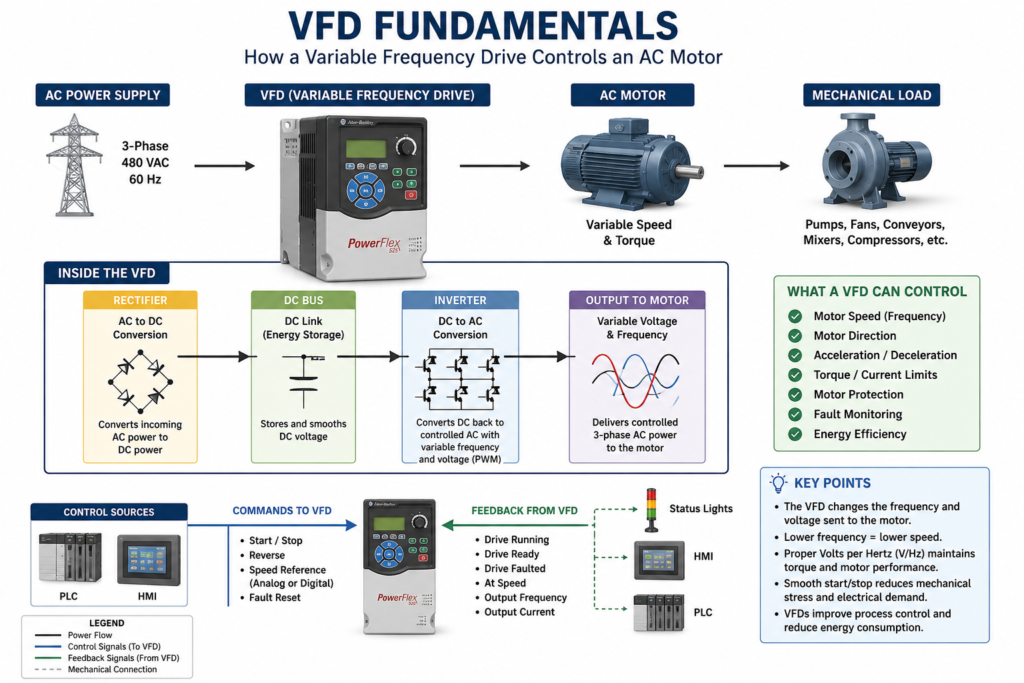
How a VFD Works Internally
A VFD may look like a simple box on the outside, but internally it performs a very important power conversion process.
Basic internal flow:
Incoming AC Power
        ↓
Rectifier
        ↓
DC Bus
        ↓
Inverter
        ↓
Controlled AC Output to Motor
1. AC Input
The VFD receives incoming AC power from the electrical supply. This may be single-phase or three-phase depending on the drive and application.
2. Rectifier
The rectifier converts incoming AC power into DC power.
The VFD lab material explains that a VFD initially converts input AC power into intermediate DC power using a rectifier bridge.
3. DC Bus
The DC bus stores and smooths the converted DC voltage. This section normally includes capacitors.
4. Inverter Section
The inverter section converts the DC bus voltage back into controlled AC power for the motor.
This output is not the same as utility sine-wave power. It is created electronically using high-speed switching, commonly through PWM.
5. Motor Output
The VFD sends controlled voltage and frequency to the motor. By changing the output frequency, the VFD changes motor speed.
Why Frequency Controls Motor Speed
For AC induction motors, speed is related to frequency and the number of motor poles.
A common formula is:
Synchronous RPM = (120 × Frequency) ÷ Number of PolesExample:
For a 4-pole motor at 60 Hz:
RPM = (120 × 60) ÷ 4
RPM = 1800 synchronous RPM
In real life, the motor may run slightly below that speed, such as 1750 RPM or 1725 RPM, because of slip.
The important point is this:
When frequency goes down, motor speed goes down.
When frequency goes up, motor speed goes up.
That is the core idea behind VFD speed control.
Why Voltage Also Matters
A VFD does not only change frequency. It also controls voltage.
For many standard AC motor applications, the drive tries to maintain a proper volts-per-hertz ratio, often written as V/Hz.
Example:
480 V ÷ 60 Hz = 8 V/HzThat means if the VFD commands 30 Hz, the drive may output approximately half voltage to maintain the proper motor magnetic field.
The volts-per-hertz ratio is generally regulated as a constant value, using 480/60 = 8 as an example, although some applications may require additional adjustment for best performance.
This matters because incorrect voltage-to-frequency control can cause:
- Poor torque
- Motor heating
- Overcurrent faults
- Poor low-speed performance
- Unstable motor operation
What Can a VFD Control?
A VFD can control several important motor behaviors.
1. Speed
The most obvious function is speed control.
A conveyor may need to slow down.
A fan may need to increase airflow.
A pump may need to maintain pressure.
A mixer may need different speeds for different recipes.
The VFD makes this possible without changing pulleys, gearboxes, or mechanical arrangements.
2. Direction
Many VFDs can reverse motor rotation electronically by changing output phase sequence internally.
This can be useful for:
- Conveyors
- Hoists
- Mixers
- Rollers
- Positioning systems
- Reversing fans, where applicable
Direction must always be applied carefully. Not every machine is mechanically safe to reverse.
3. Acceleration
A VFD can ramp the motor from zero speed to commanded speed over a programmed time.
Example:
Acceleration Time = 10 secondsInstead of starting instantly, the motor smoothly accelerates over 10 seconds.
This helps reduce:
- Mechanical shock
- Belt stress
- Coupling stress
- Inrush current
- Product movement issues
4. Deceleration
A VFD can also ramp the motor down when stopping.
Example:
Deceleration Time = 15 secondsThe drive reduces motor frequency and voltage gradually until the motor stops.
A VFD stopping sequence ramps down frequency and voltage at a controlled rate, and that additional braking torque may require a braking circuit.
5. Torque and Current Limits
VFDs can usually be configured with current limits, torque limits, overload settings, and protection functions.
This helps protect:
- The drive
- The motor
- The machine
- The process
- The electrical system
This is one reason why entering correct motor nameplate data into the VFD is so important.
6. Fault Monitoring
A VFD constantly monitors itself and the motor circuit.
Common VFD faults include:
| Fault Type | Possible Meaning |
|---|---|
| Overcurrent | Current exceeded drive limit |
| Overvoltage | DC bus voltage too high |
| Undervoltage | Supply voltage or DC bus too low |
| Motor overload | Motor current/load too high for too long |
| Ground fault | Leakage or short to ground |
| Overtemperature | Drive heatsink or internal temperature too high |
| Communication loss | PLC/network communication problem |
| Analog input loss | Speed reference signal missing |
A PowerFlex manual, for example, includes chapters for installation, start-up, programming, parameters, drive status, faults, fault descriptions, and corrective actions.
Common Industrial Applications
VFDs are used in many industrial systems.
Pumps
VFDs are commonly used to control flow or pressure. Instead of running a pump at full speed and using a valve to restrict flow, the VFD can slow the motor down.
Applications:
- Water systems
- Chemical transfer
- CIP systems
- Cooling systems
- Process pumps
Fans and Blowers
Fans are one of the best applications for VFDs because speed control can reduce energy use and improve process control.
Applications:
- HVAC supply fans
- Exhaust fans
- Cooling fans
- Combustion air blowers
- Dust collection systems
Conveyors
VFDs allow conveyors to start smoothly, stop smoothly, and run at controlled speeds.
Applications:
- Packaging lines
- Sorting systems
- Accumulation conveyors
- Filling lines
- Inspection stations
Mixers and Agitators
VFDs can control mixing speed based on product, recipe, viscosity, or process step.
Applications:
- Tanks
- Homogenizers
- Blenders
- Chemical mixing
- Food and beverage processing
Compressors and Process Equipment
Some compressors and production machines use VFDs to match motor speed to actual demand.
Applications:
- Air compressors
- Vacuum pumps
- Process skids
- Machine centers
- Automated production lines
Local Control vs Remote Control
A VFD can be controlled locally or remotely.
Local Control
Local control usually means the operator or technician controls the drive directly from the keypad or HIM.
Typical local functions:
- Start
- Stop
- Change speed
- View output frequency
- View output current
- View fault codes
- Reset faults
- Change parameters
This is useful during maintenance, setup, testing, and troubleshooting.
Remote Control
Remote control means the VFD receives commands from external devices.
Examples:
| Remote Signal | Purpose |
|---|---|
| Digital Input | Start, Stop, Reverse, Jog, Fault Reset |
| Analog Input | Speed reference, pressure feedback, flow feedback |
| Digital / Relay Output | Running, Faulted, At Speed, Ready |
| Analog Output | Output frequency, motor current, speed feedback |
| Network Communication | Start command, speed reference, status, fault code |
Remote control signals are typically wired into the VFD terminal strip and can include digital inputs, analog inputs, digital/relay outputs, and analog outputs.
What Is a HIM?
HIM stands for:
Human Interface Module
A HIM is the operator interface for the drive. Depending on the drive model, the HIM may be built into the drive or mounted remotely on the panel door.
A HIM may allow a technician to:
- Start and stop the drive
- Adjust speed
- View parameters
- View faults
- Reset faults
- Upload or download configuration
- Copy parameters from one drive to another, if supported
- Monitor output frequency, current, voltage, and drive status
In the field, the HIM is extremely useful because it gives the technician direct access to the drive without needing a laptop.
VFD and PLC Relationship
In automation systems, the PLC usually does not directly power the motor. Instead, the PLC sends commands to the VFD, and the VFD controls the motor.
A simple control relationship looks like this:
PLC Command → VFD → Motor
VFD Feedback → PLC → HMI / Alarm Logic
Example PLC commands:
VFD_Start_Cmd
VFD_Stop_Cmd
VFD_Reset_Cmd
VFD_Speed_Reference
Example VFD feedback:
VFD_Running
VFD_Ready
VFD_Faulted
VFD_At_Speed
VFD_Output_Frequency
VFD_Output_Current
This allows the PLC and HMI to monitor the drive and give the operator clear information.
Important VFD Parameters
Every VFD manufacturer uses slightly different parameter names, but the concepts are usually similar.
| Parameter Concept | Purpose |
|---|---|
| Motor Rated Voltage | Matches the drive to the motor nameplate voltage |
| Motor Rated Current / FLA | Protects the motor from overload |
| Motor Rated Frequency | Usually 50 Hz or 60 Hz |
| Minimum Frequency | Lowest allowed motor speed |
| Maximum Frequency | Highest allowed motor speed |
| Acceleration Time | Time to ramp up |
| Deceleration Time | Time to ramp down |
| Start Source | Defines where the run command comes from |
| Speed Reference | Defines where the speed command comes from |
| Stop Mode | Defines how the motor stops |
| Digital Input Functions | Defines what each input does |
| Relay Output Functions | Defines status outputs such as running or faulted |
| Communication Settings | Defines network address, baud rate, protocol, or Ethernet settings |
A technician should never replace or reset a VFD without first understanding these parameters.
Why VFD Backups Matter
A VFD is not just hardware. It also contains configuration.
If a drive fails and the replacement drive is installed with default parameters, the motor may not run correctly.
Possible issues:
- Wrong motor voltage
- Wrong motor FLA
- Wrong start source
- Wrong speed reference
- Wrong acceleration time
- Wrong deceleration time
- Wrong digital input functions
- Wrong relay output functions
- Wrong communication settings
- Wrong direction
- Wrong min/max speed
That is why backing up the drive configuration is an important part of professional maintenance.
Backup methods may include:
- Manual parameter list
- HIM CopyCat function, if supported
- DriveTools SP or similar vendor software
- DriveExplorer
- Connected Components Workbench
- Manufacturer-specific software
- Printed parameter record
- PLC or maintenance documentation
Technician Note: Do Not Treat Every VFD the Same
The concept of a VFD is universal, but the details are not always the same.
Different manufacturers may use different names for:
- Parameters
- Keypad menus
- Fault codes
- Wiring terminals
- Communication settings
- Backup methods
- Stop modes
- Safety functions
Always verify the specific manual for the installed drive before making changes.
A PowerFlex 4 manual, for example, states that the manual is intended for qualified personnel who can program and operate adjustable frequency AC drive devices and understand parameter settings and functions.
Safety Reminder
VFDs contain dangerous voltage.
Even after power is removed, internal capacitors can remain charged for a period of time. Never assume that a blank display means the drive is safe to touch.
A PowerFlex manual warns that the drive contains high-voltage capacitors that require time to discharge after removing mains supply, and that dark display LEDs do not indicate the capacitors are discharged.
Always follow:
- Lockout/Tagout procedures
- Electrical safety rules
- Plant safety procedures
- Manufacturer instructions
- Proper PPE requirements
- Qualified-personnel requirements
Basic VFD Troubleshooting Mindset
When troubleshooting a VFD, avoid simply pressing reset over and over.
A better approach is:
Fault Code → Meaning → Possible Cause → Field Check → Corrective Action → Controlled RestartGood questions to ask:
- What fault is displayed?
- Did the motor actually trip, or did the drive lose a command?
- Is the drive in local or remote mode?
- Is the speed reference present?
- Is the start command present?
- Is the drive ready?
- Is there a safety interlock open?
- Is the motor overloaded?
- Is the input voltage correct?
- Is the motor wiring correct?
- Did this happen during start, run, or stop?
- Did the problem happen after a replacement or parameter change?
This troubleshooting mindset will prevent unnecessary drive replacements.
Common Mistakes Technicians Should Avoid
Avoid these common VFD mistakes:
- Replacing a drive without backing up parameters
- Assuming the new drive will work with default settings
- Ignoring motor nameplate data
- Resetting faults without identifying the cause
- Confusing start source with speed reference
- Mixing up local and remote control
- Forgetting communication settings
- Changing acceleration/deceleration without understanding the load
- Running a motor too slowly without considering cooling
- Not checking grounding and shielded wiring
- Disconnecting the motor from the VFD output as a normal control method
- Assuming every VFD brand uses the same terminology
Quick Field Checklist
Before working with a VFD, verify:
[ ] Correct drive model
[ ] Correct input voltage
[ ] Correct motor voltage
[ ] Correct motor FLA
[ ] Correct motor HP/kW
[ ] Correct start source
[ ] Correct speed reference
[ ] Correct min/max frequency
[ ] Correct acceleration and deceleration time
[ ] Correct stop mode
[ ] Correct digital input configuration
[ ] Correct relay output configuration
[ ] Correct communication settings
[ ] Fault history reviewed
[ ] Parameter backup saved
[ ] Safety procedures followed
Final Thoughts
A VFD is much more than a motor speed controller. It is a complete electronic motor control device that manages speed, acceleration, deceleration, torque, current, direction, protection, feedback, and communication.
For an automation technician, understanding VFDs is a major skill. It helps with troubleshooting, commissioning, replacing drives, working with PLCs, reading HMI information, and understanding how the process is actually being controlled.
The best way to learn VFDs is to understand the fundamentals first:
Frequency controls speed.
Voltage supports torque.
Parameters define behavior.
Inputs provide commands.
Outputs provide feedback.
Faults tell the story.
Backups protect the process.
Once these basics make sense, troubleshooting and configuring VFDs becomes much easier.