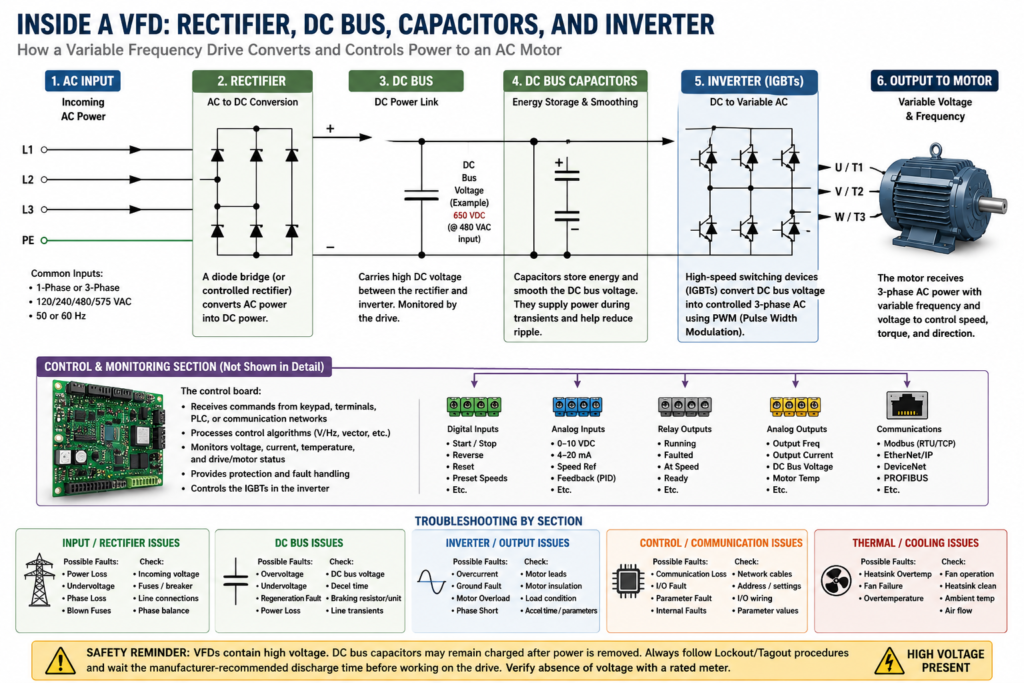
2. Inside a VFD: Rectifier, DC Bus, Capacitors, and Inverter (2 of 19)
Introduction
A Variable Frequency Drive may look like a simple electronic box mounted inside a control panel, but internally it performs a very important power conversion process.
A VFD does not simply “lower voltage” to slow down a motor. Instead, it takes incoming AC power, converts it to DC, stores and smooths that DC energy, and then electronically creates a new controlled AC output for the motor.
Understanding this internal process helps an automation technician troubleshoot problems such as:
- Undervoltage faults
- Overvoltage faults
- Ground faults
- Overcurrent faults
- Motor overload faults
- Regeneration problems
- Braking issues
- Noise and grounding problems
- Output waveform problems
The examples in this post use Allen-Bradley PowerFlex drives as a practical reference, but the same basic internal sections exist in most industrial VFDs regardless of manufacturer.
The Basic Power Flow Inside a VFD
The internal power flow of a VFD can be simplified like this:
Incoming AC Power
        ↓
Rectifier
        ↓
DC Bus
        ↓
DC Bus Capacitors
        ↓
Inverter / Output Section
        ↓
Controlled AC Output to Motor
A VFD initially converts the input AC power into intermediate DC power using a rectifier bridge. It also notes that the VFD controls voltage and frequency to operate the motor.
A technician should understand this flow because many VFD faults are connected to one of these internal sections.
1. Incoming AC Power
The first section of the VFD receives the incoming line power.
Depending on the drive and application, the input may be:
- 120 VAC single-phase
- 240 VAC single-phase
- 240 VAC three-phase
- 480 VAC three-phase
- 575 VAC three-phase
- 690 VAC three-phase, in some industrial applications
In most industrial environments, VFDs are commonly used with three-phase induction motors. The drive may receive single-phase or three-phase input depending on the design, but the output to the motor is typically three-phase.
When using single-phase power, the drive may need to be derated because only part of the rectifier is carrying the entire load.
Technician Note: Input Side vs Output Side
It is important to separate the VFD into two sides:
| Side | Description |
|---|---|
| Line Side | Incoming power feeding the VFD |
| Load Side | Output power from VFD to motor |
This matters because troubleshooting the input side is not the same as troubleshooting the output side.
Example:
Input problem = incoming voltage, phase loss, fuses, breaker, line reactor, disconnect
Output problem = motor cable, motor insulation, ground fault, overload, overcurrent
A common mistake is replacing a VFD before confirming whether the problem is actually on the line side, load side, motor, or control circuit.
2. Rectifier Section
The rectifier is the first major internal section of the VFD.
Its job is to convert incoming AC power into DC power.
What the Rectifier Does
AC power alternates direction many times per second. In the United States, this is normally 60 Hz. A rectifier uses semiconductor devices, commonly diodes or controlled rectifier components depending on the drive design, to allow current to flow in one direction and create DC voltage.
A glossary definition describes a bridge rectifier as a full-wave rectifier that conducts current in only one direction, where AC applied to the bridge rectifier results in DC at the output.
Simple view:
AC Input → Rectifier → DC OutputThe rectifier does not yet create the final motor waveform. It only creates the DC power needed by the next stage.
Why the Rectifier Matters for Troubleshooting
Problems related to the rectifier/input section can cause faults such as:
- Power loss
- Undervoltage
- Input phase loss
- Blown fuses
- DC bus undervoltage
- Drive not powering up
- Nuisance trips during starting
If the drive display powers up but faults immediately, the technician should not assume the inverter section is bad. The issue may be incoming voltage, fuses, line disturbances, or rectifier-related damage.
3. DC Bus
After the rectifier converts AC into DC, the power enters the DC bus.
The DC bus is the internal DC power link between the rectifier and inverter sections.
Simple view:
Rectifier → DC Bus → InverterThe DC bus is very important because the inverter uses this DC voltage to create the controlled AC output to the motor.
What Is DC Bus Voltage?
The DC bus voltage is normally higher than the incoming AC RMS voltage.
For example:
| Input Voltage | Approximate DC Bus Voltage |
|---|---|
| 240 VAC | Around 325 VDC |
| 480 VAC | Around 650 VDC |
These are approximate values. The actual DC bus voltage depends on drive design, input voltage, load, and operating condition.
This is why VFDs are dangerous even after incoming power is removed. The DC bus capacitors can remain charged for a period of time.
Why DC Bus Voltage Matters
The DC bus is monitored by the drive. If the bus voltage is too low or too high, the VFD can fault.
Common DC bus-related faults include:
| Fault | Basic Meaning |
|---|---|
| Undervoltage | DC bus voltage fell too low |
| Overvoltage | DC bus voltage rose too high |
| Power loss | DC bus voltage dropped due to input power issue |
| Regeneration fault | Load pushed energy back into the drive |
Faults such as Power Loss, UnderVoltage, and OverVoltage. It describes Power Loss as a condition where the DC bus remained below a percentage of nominal voltage, UnderVoltage as the DC bus falling below minimum value, and OverVoltage as the DC bus exceeding the maximum value.
4. DC Bus Capacitors
The DC bus capacitors are one of the most important parts inside a VFD.
Their job is to store energy and smooth the DC voltage.
What Capacitors Do
A capacitor stores electrical charge. In a VFD, DC bus capacitors help reduce ripple and provide a more stable DC voltage for the inverter section.
A glossary definition explains that a capacitor stores electrical charge on internal plates and is rated by capacitance and maximum voltage.
In simple terms:
Rectifier creates DC.
Capacitors smooth and store that DC.
Inverter uses that DC to create motor output.
Why Capacitors Are Dangerous
Even when the VFD input power is removed, the DC bus capacitors may still hold a dangerous charge.
This is one of the most important safety concepts when working with VFDs.
Never assume a drive is safe just because:
- The display is off
- The keypad is blank
- The motor stopped
- The disconnect is off
- The contactor is open
Bus capacitor discharging and capacitor safety, and the manual includes precautions about capacitor discharge before working on the drive.
Technician Note: Always Follow the Manual
Before opening or servicing any VFD:
1. Follow Lockout/Tagout.
2. Remove incoming power.
3. Wait the manufacturer-required discharge time.
4. Verify absence of voltage with a properly rated meter.
5. Follow plant electrical safety procedures.
Different drives may have different discharge times. Always verify the specific manual for the installed drive.
5. Inverter Section
The inverter is the output section of the VFD.
Its job is to take the DC bus voltage and create a controlled AC output for the motor.
A glossary definition describes the inverter as the output portion of an adjustable frequency drive that converts the DC bus into output AC whose frequency is controlled by the drive’s control circuitry.
Simple view:
DC Bus → Inverter → Controlled AC OutputHow the Inverter Controls Motor Speed
The inverter uses high-speed switching devices to create a motor output waveform.
Modern VFDs commonly use IGBTs, or insulated gate bipolar transistors, in the inverter section.
The VFD does not output a perfect utility sine wave. Instead, it creates a high-speed switching waveform that the motor responds to as controlled voltage and frequency.
This is commonly called:
PWM = Pulse Width ModulationWhat Is PWM?
PWM stands for Pulse Width Modulation.
The drive rapidly switches the output transistors ON and OFF to create an effective AC waveform for the motor.
The important idea is:
The VFD controls the output frequency to control motor speed.
The VFD controls the output voltage to support motor torque.
A glossary definition describes carrier frequency in a PWM inverter as the fixed rate at which voltage pulses are provided to the motor, with common carrier frequencies from 1 kHz through 16 kHz.
6. Output to Motor
The final output of the VFD goes to the motor terminals.
Typical VFD output terminals may be labeled:
U / T1
V / T2
W / T3
The PowerFlex 400 terminal data shows input terminals such as R/L1, S/L2, T/L3 and motor output terminals such as U/T1, V/T2, and W/T3. It also notes that switching any two motor leads changes forward direction.
The VFD output is variable voltage and variable frequency.
Example:
| Commanded Speed | Possible Output |
|---|---|
| Stopped | 0 Hz |
| Low speed | 10 Hz |
| Half speed | 30 Hz |
| Full base speed | 60 Hz |
| Above base speed | Above 60 Hz, if allowed |
Important: Do Not Treat VFD Output Like Normal Line Power
The output of a VFD is electronically generated. It should not be treated exactly like standard incoming AC line power.
Avoid these mistakes:
- Do not install random contactors on the VFD output without understanding the application.
- Do not open/close the motor circuit under load as normal control.
- Do not megger a motor while connected to the drive.
- Do not connect power factor correction capacitors on the VFD output unless the manufacturer specifically allows it.
- Do not run excessive motor lead lengths without checking the manual.
- Do not ignore grounding and shielding.
VFDs are intended to be commanded by control input signals, and that disconnecting and reapplying output power to the motor should not be used as normal control. If that type of device is necessary, such as for Emergency Stop situations, auxiliary contacts should simultaneously disable the drive run command.
7. The Control Board and Microprocessor
Besides the power section, a VFD also has a control section.
This section includes the electronics that manage:
- Keypad/HIM interface
- Digital inputs
- Analog inputs
- Relay outputs
- Analog outputs
- Communication ports
- Parameter storage
- Fault monitoring
- Motor control algorithm
- Acceleration and deceleration
- Current limits
- Protection logic
The VFD training material notes that an embedded microprocessor governs the overall operation of the VFD controller, while users can configure the drive through parameter adjustments for specific applications.
This is why parameters matter so much. The hardware may be correct, but wrong parameters can make the application fail.
8. How All Sections Work Together
Here is the complete sequence:
1. AC power enters the VFD.
2. The rectifier converts AC to DC.
3. The DC bus carries the DC voltage.
4. Capacitors store and smooth the DC energy.
5. The inverter converts DC back into controlled AC.
6. The motor receives variable voltage and frequency.
7. The control board monitors commands, feedback, current, voltage, and faults.
A simple way to remember it:
Rectifier = AC to DC
DC Bus = internal DC link
Capacitors = store and smooth energy
Inverter = DC back to controlled AC
Motor = converts electrical energy into motion
Why This Matters for Troubleshooting
When a VFD faults, it helps to think about which internal section may be involved.
Input / Rectifier Side Problems
Possible symptoms:
- Drive will not power up
- Input fuse blows
- Power loss fault
- Undervoltage fault
- Phase loss
- DC bus too low
Possible checks:
[ ] Incoming voltage
[ ] Input fuses
[ ] Breaker/disconnect
[ ] Line reactor
[ ] Loose input terminals
[ ] Phase imbalance
[ ] Grounding
DC Bus Problems
Possible symptoms:
- Overvoltage fault
- Undervoltage fault
- Power ride-through issues
- Fault during deceleration
- Fault during high inertia stopping
Possible checks:
[ ] Incoming voltage
[ ] Deceleration time
[ ] Regenerative load condition
[ ] Dynamic braking resistor
[ ] Braking transistor
[ ] DC bus reading
[ ] Line transients
The PowerFlex troubleshooting table notes that overvoltage can be caused by high line voltage, transient conditions, or motor regeneration. It recommends extending deceleration time or installing a dynamic brake option when regeneration causes bus overvoltage.
Inverter / Output Side Problems
Possible symptoms:
- Overcurrent fault
- Ground fault
- Motor overload
- Motor stalled
- Phase-to-phase short
- Phase-to-ground short
- Motor will not accelerate
Possible checks:
[ ] Motor leads
[ ] Motor insulation
[ ] Ground fault
[ ] Mechanical load
[ ] Acceleration time
[ ] Current limit
[ ] Boost settings
[ ] Motor FLA parameter
[ ] Output cable length
The troubleshooting table lists Motor Stalled as a condition where the drive is unable to accelerate the motor, and Hardware OverCurrent as output current exceeding the hardware current limit.
Common Faults Related to Internal VFD Sections
| VFD Section | Possible Faults | What to Think About |
|---|---|---|
| Input / Rectifier | Power Loss, Undervoltage | Incoming power, fuses, line voltage |
| DC Bus | Overvoltage, Undervoltage | Decel time, regeneration, line transients |
| Capacitors | Bus instability, failure to hold charge | Age, heat, ripple, internal damage |
| Inverter | Overcurrent, Ground Fault, Phase Short | Motor wiring, motor insulation, load |
| Control Board | Communication Loss, Parameter Fault | Network, firmware, I/O, keypad/HIM |
| Cooling System | Heatsink Overtemperature | Fan, dust, ambient temperature |
Overvoltage Example
A common field scenario:
A conveyor or high-inertia load is stopping too fast.
The motor acts like a generator during deceleration.
Energy flows back into the VFD.
The DC bus voltage rises.
The drive trips on OverVoltage.
Possible corrective actions:
[ ] Increase deceleration time.
[ ] Check braking resistor.
[ ] Verify braking transistor / braking unit.
[ ] Check line voltage.
[ ] Check for mechanical overhauling load.
[ ] Verify stop mode.
This is why overvoltage is not always caused by high incoming power. Sometimes the motor/load is pushing energy back into the drive.
Undervoltage Example
Another common field scenario:
The drive starts.
The motor load increases.
Incoming voltage drops.
The DC bus falls below minimum.
The drive trips on UnderVoltage.
Possible corrective actions:
[ ] Check incoming voltage under load.
[ ] Check fuses and disconnect.
[ ] Check loose terminals.
[ ] Check transformer capacity.
[ ] Check for phase loss.
[ ] Check supply voltage tolerance.
The PowerFlex troubleshooting information recommends monitoring the incoming AC line for low voltage or line power interruption when an undervoltage condition occurs.
Overcurrent Example
A drive may trip on overcurrent during start-up.
Possible causes:
[ ] Acceleration time too short
[ ] Load too heavy
[ ] Motor mechanically jammed
[ ] Incorrect motor data
[ ] Incorrect boost setting
[ ] Motor cable problem
[ ] Ground fault
[ ] Shorted motor winding
The PowerFlex troubleshooting table recommends checking programming, excess load, boost settings, DC brake voltage, and other causes of excess current for hardware overcurrent faults.
Technician Notes
1. The VFD Is Not Just One Device Internally
When troubleshooting, think in sections:
Input → Rectifier → DC Bus → Inverter → MotorThis makes troubleshooting more logical.
2. The DC Bus Is the Heart of the Drive
Many faults relate directly or indirectly to the DC bus.
Examples:
- Undervoltage
- Overvoltage
- Power loss
- Regeneration
- Braking issues
If the DC bus is unstable, the drive cannot properly control the motor.
3. The Inverter Controls the Motor, Not the Input Line
The motor is not directly connected to the incoming line while running from the VFD. The motor is connected to the VFD output section.
That output is electronically generated by the inverter.
4. The Motor Can Push Energy Back Into the Drive
During deceleration or overhauling loads, the motor can act like a generator.
This is why fast deceleration can cause overvoltage faults.
5. Heat Is a Major Enemy
Heat affects:
- Capacitors
- Power transistors
- Control boards
- Cooling fans
- Drive life
A dirty heatsink or failed fan can cause nuisance faults or permanent damage.
Field Checklist: Understanding the Internal VFD Sections
When troubleshooting a VFD, use this quick mental checklist:
[ ] Is the incoming AC voltage correct?
[ ] Are all input phases present?
[ ] Are fuses and disconnects OK?
[ ] Is the drive powering up normally?
[ ] Is the DC bus voltage stable?
[ ] Does the fault happen during start, run, or stop?
[ ] Does the fault happen during acceleration?
[ ] Does the fault happen during deceleration?
[ ] Is the motor load mechanically free?
[ ] Are motor leads connected correctly?
[ ] Is there a ground fault?
[ ] Is the motor FLA programmed correctly?
[ ] Is the acceleration/deceleration time reasonable?
[ ] Is braking required for this application?
[ ] Is the drive fan/heatsink clean?
Simple Technician Explanation
A good way to explain a VFD internally is:
A VFD takes fixed AC power from the plant,
converts it into DC,
stores it on the DC bus,
then electronically creates a new AC output
with the voltage and frequency needed to control the motor.
Or even shorter:
AC in → DC inside → controlled AC outThat is the basic internal operation of a VFD.
Common Mistakes to Avoid
Avoid these mistakes when working with VFDs:
[ ] Assuming the output is normal sine-wave utility power
[ ] Opening the motor circuit while the VFD is running
[ ] Ignoring capacitor discharge time
[ ] Resetting overvoltage faults without checking deceleration
[ ] Resetting overcurrent faults without checking the motor/load
[ ] Forgetting that regeneration can raise the DC bus
[ ] Using default parameters after replacing a drive
[ ] Ignoring cooling fans and heatsinks
[ ] Mixing up line-side and load-side troubleshooting
[ ] Assuming all VFD brands use the same terminal labels
Final Thoughts
Understanding the inside of a VFD makes troubleshooting much easier.
Instead of seeing the VFD as a mystery box, think of it as a power conversion system:
Rectifier: converts AC to DC
DC Bus: carries internal DC power
Capacitors: store and smooth energy
Inverter: creates controlled AC output
Control Board: manages commands, feedback, and protection
For an automation technician, this knowledge is extremely valuable. When a drive faults, you can start asking better questions:
Is this an input power problem?
Is this a DC bus problem?
Is this a braking/regeneration problem?
Is this an inverter/output problem?
Is this a motor/load problem?
Is this a parameter/control problem?
That mindset is what separates guessing from real troubleshooting.