PLC Troubleshooting Basics: A Practical Flowchart Approach for Beginners
When a PLC-controlled machine stops working, the problem is not always in the ladder logic. Many times, the real issue is related to power, field wiring, sensors, output devices, I/O modules, communication, or even something simple that happened during operation.
A good technician should avoid guessing and follow a structured troubleshooting process.
This post is based on a simple but powerful idea:
Recognize the symptom, isolate the problem, and take corrective action.
That is the foundation of effective troubleshooting.
1. Start With the Operator
Before opening the electrical panel or connecting to the PLC, start by asking questions.
The operator is usually the first person who saw the problem happen. They may know:
- What the machine was doing before it stopped
- Whether an alarm appeared on the HMI
- If the issue happened suddenly or gradually
- If the problem repeats during the same part of the cycle
- If someone recently adjusted, cleaned, or worked near the equipment
Always include operator feedback. The troubleshooting material also reinforces that questioning the operator is part of the process when diagnosing a PLC-managed system.
In a real plant environment, this step can save a lot of time.
2. Check the PLC Power and Status Lights
After gathering information, check the PLC status indicators.
Typical things to look for include:
| PLC Indicator | What It May Tell You |
|---|---|
| Power / DC Power | PLC power supply status |
| Run | Processor is executing the program |
| Fault | Processor or system fault |
| I/O Fault | Possible module or rack issue |
| Battery Low | Backup battery may need replacement |
| Communication | Network or device communication status |
If the PLC does not have power, do not immediately assume the processor is bad. Start with the basics: incoming power, fuses, power supply, and wiring.
Start with power light, AC supply, fuse condition, and power supply replacement before moving deeper into the system.
3. Verify the Power Supply, Fuses, and AC Service
A PLC system depends on clean and stable power.
If the PLC power light is off, check:
- Main disconnect
- Control transformer
- Power supply input voltage
- Fuses or circuit breakers
- 24 VDC power supply output
- Loose terminals
- Grounding issues
If DC Power LED is not on, the DC power supply may be off because of a bad power supply or possibly fuses.
This is why the first stage of troubleshooting should always be electrical verification, not software changes.
4. Check Processor Status and Error Codes
If the PLC has power but the machine is still down, check the processor status.
Look for:
- Processor fault
- Memory fault
- I/O fault
- Battery low indication
- Communication fault
- Major or minor fault codes
If an error code is displayed, do not guess. Look up the fault in the proper manual or software diagnostic tool.
A processor fault light usually indicates that a fault exists within the processor, while a memory fault may indicate an issue between the memory module and the processor module.
In Allen-Bradley systems, this may involve checking controller properties, fault logs, module status, or diagnostic buffers depending on the PLC platform.
5. Understand the PLC Scan
To troubleshoot PLC logic correctly, you need to understand the PLC scan.
A basic PLC scan can be understood in three steps:
- The processor reads the input image table.
- The processor executes the user program.
- The processor updates the output image table.
Three-step scan process and notes that scan order and scan time can affect program operation, especially with high-speed devices.
This is important because a field device may change state faster than the PLC can detect it, or logic may appear confusing if you do not understand when inputs and outputs are updated.
6. Check the I/O Status
One of the most important troubleshooting skills is comparing the real-world device to what the PLC sees.
For inputs, ask:
- Is the sensor physically activated?
- Is voltage reaching the input terminal?
- Is the input LED turning on?
- Does the PLC input bit change in the software?
- Is the correct input address being used in the logic?
For outputs, ask:
- Is the PLC logic enabling the output?
- Is the output LED turning on?
- Is voltage leaving the output module?
- Is the field device receiving voltage?
- Is the device itself working?
I/O modules act as the “eyes, ears, and hands” of the programmable controller because they connect real-world sensing devices and work devices to the control system.
That is a powerful way to think about troubleshooting:
If the PLC cannot “see” the input, it cannot make the right decision.
If the PLC cannot “move” the output, the machine will not respond.
7. Separate Logic Problems From Field Problems
A common mistake is blaming the PLC program too quickly.
When an output device does not operate, use the programming software to verify whether the logic is actually commanding the output. The troubleshooting material states that a quick check with a programming device can indicate whether the program logic is enabling the output.
If the logic is not enabling the output, then troubleshoot the program conditions:
- Interlocks
- Permissives
- Fault bits
- Mode selection
- Safety status
- Limit switches
- Sensor feedback
- Sequence step logic
If the logic is enabling the output but the device does not operate, then troubleshoot the field side:
- Output module
- Fuse
- Relay
- Contactor
- Solenoid
- Motor starter
- Wiring
- Terminal blocks
- Device power
This separation is critical.
8. Check Field Devices and Wiring
Many PLC problems are actually field device or wiring problems.
Examples include:
- Failed proximity sensor
- Misaligned photoeye
- Damaged cable
- Loose terminal
- Blown fuse
- Failed relay
- Stuck limit switch
- Bad solenoid coil
- Open neutral or common
- Shorted output device
If there is no voltage reading at the input module, the input device or field wiring can be the source of the problem.
This is why voltage checks at the module and at the field device are so important.
9. Check I/O Modules and Backplane
If the field device and wiring are good, move deeper into the PLC hardware.
Check:
- Module status LEDs
- Slot configuration
- I/O fault status
- Rack or chassis condition
- Backplane connection
- Removable terminal block seating
- Communication adapter status
- Module keying or mismatch
Check the I/O device and wiring first, then checking the I/O module, and finally checking the rack or backplane if the problem continues.
This order makes sense because modules are usually not the first thing to fail. Always verify the field side before replacing PLC hardware.
10. Do Not Bypass Safety
Troubleshooting must be done safely.
Hardwired safety devices such as E-Stops, safety relays, guard switches, and motor disconnects should not be treated like normal PLC inputs.
A hardwired emergency stop circuit is recommended because it provides a redundant method of stopping outputs that is independent of the PLC program.
This is a key industrial concept:
Safety should not depend only on PLC logic.
When troubleshooting outputs, always consider stored energy, unexpected motion, pneumatic pressure, hydraulic pressure, motor rotation, and machine guarding.
11. Use a Systematic Troubleshooting Method
A strong troubleshooting method usually follows this path:
| Step | Action |
|---|---|
| 1 | Identify the symptom |
| 2 | Talk to the operator |
| 3 | Check power and status LEDs |
| 4 | Review fault codes or alarms |
| 5 | Verify PLC inputs |
| 6 | Verify PLC logic conditions |
| 7 | Verify PLC outputs |
| 8 | Check wiring and field devices |
| 9 | Check I/O modules |
| 10 | Correct the issue and retest |
Systematic troubleshooting as symptom recognition, problem isolation, and corrective action.
That simple structure is what separates guessing from professional troubleshooting.
Technician Mindset
A good PLC technician does not just connect to the PLC and start changing logic.
A good technician asks:
- What changed?
- What should be happening?
- What is actually happening?
- What does the PLC see?
- What is the PLC commanding?
- Is the field device responding?
- Is the issue electrical, mechanical, pneumatic, network-related, or logic-related?
The goal is not to replace parts randomly. The goal is to prove where the failure is.
Final Thoughts
PLC troubleshooting is not only about ladder logic. It is a combination of electrical knowledge, control logic, field devices, machine sequence, safety circuits, and good observation.
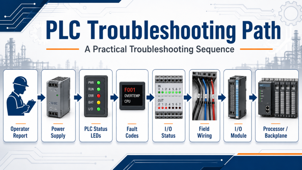
The best approach is to slow down, follow the evidence, and move step by step:
Power → Processor → Program → Inputs → Outputs → Wiring → Field Devices → I/O Modules → Backplane
For beginners, this method builds confidence. For experienced technicians, it prevents wasted time and unnecessary part replacement.
In real industrial environments, a structured troubleshooting process can be the difference between a long downtime event and a quick recovery.