23. Faults vs Alarms
In industrial automation, the words fault and alarm are often used together.
But they do not always mean the same thing.
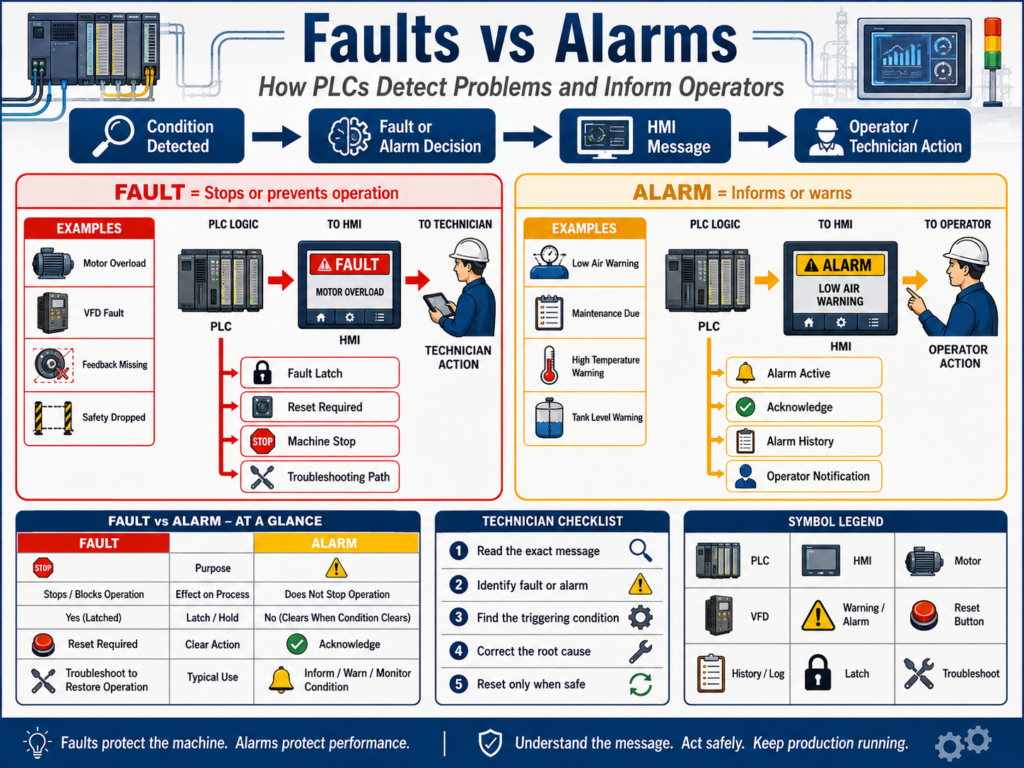
A fault usually means something is wrong enough to stop equipment, block operation, or require a reset.
An alarm usually means the operator or technician needs to be notified about a condition.
Simple idea:
Fault = Stops or prevents operation
Alarm = Informs or warns the operator
Understanding the difference between faults and alarms helps automation technicians troubleshoot machines faster and understand PLC logic more clearly.
1. Why This Difference Matters
If every warning stops the machine, production becomes unstable.
If serious faults only show as warnings, the machine may continue running in an unsafe or damaging condition.
That is why PLC logic should clearly separate:
Fault conditions
Alarm conditions
Warning conditions
Status messages
Operator notifications
A professional automation system should answer:
Is this condition dangerous?
Can the machine continue running?
Should the equipment stop immediately?
Should the operator only be notified?
Does this condition require a reset?
Should this be shown on the HMI?
Should this be recorded in alarm history?
This makes machine behavior easier to understand.
2. What Is a Fault?
A fault is an abnormal condition that usually stops equipment or prevents it from starting.
Simple definition:
Fault = A problem that stops or disables operation.Examples:
Motor overload tripped
VFD faulted
Safety relay dropped
Motor feedback missing
Cylinder failed to extend
Door failed to close
High pressure fault
Low tank level fault
Analog signal lost
Communication fault
Emergency stop active
A fault often requires:
Fault detection
Fault latch
Machine stop or output disable
HMI message
Correction of the problem
Reset action
A fault is more serious than a simple warning.
3. What Is an Alarm?
An alarm is a notification that tells the operator or technician something needs attention.
Simple definition:
Alarm = A condition that informs or warns.Examples:
Low air pressure warning
High temperature warning
Tank level low warning
VFD warning active
Maintenance due
Filter differential pressure high
Sensor dirty warning
Product count target reached
Runtime exceeded
An alarm may or may not stop the machine.
Some alarms are informational.
Some alarms warn before a fault happens.
Some alarms tell the operator that action is required soon.
4. Simple Difference
| Concept | Purpose | Typical Machine Action |
|---|---|---|
| Fault | Protect equipment, process, or people | Stop, block, latch, require reset |
| Alarm | Notify operator or maintenance | Display message, log event, may continue running |
Simple memory trick:
Fault = action required before operation can continue
Alarm = attention required, but not always a stop
5. Fault Example: Motor Feedback Fault
A common motor fault is a feedback fault.
Example:
PLC commands motor to run.
Motor feedback does not turn ON within 3 seconds.
PLC latches Motor Feedback Fault.
Motor command is disabled.
HMI shows fault message.
Operator or technician must correct issue and reset.
PLC concept:
Motor_Run_Command = ON
AND Motor_Running_Feedback = OFF
FOR 3 seconds
= Motor_Feedback_Fault
Possible causes:
Contactor did not pull in
VFD did not run
Overload tripped
Broken feedback wire
Bad auxiliary contact
Bad PLC input
No control voltage
This should usually be a fault because the machine expected motion, but proof of motion did not happen.
6. Alarm Example: Low Air Pressure Warning
A low air pressure warning may be an alarm before it becomes a fault.
Example:
Normal air pressure = 80 PSI
Warning alarm = below 70 PSI
Fault = below 60 PSI
Logic concept:
Air_Pressure < 70 PSI = Low Air Pressure Alarm
Air_Pressure < 60 PSI = Low Air Pressure Fault
This allows the operator to react before the machine stops.
The alarm gives early warning.
The fault protects the machine when the condition becomes too severe.
7. Faults Are Often Latched
Many faults should be latched.
A latched fault stays ON even if the original condition disappears.
Why?
Because faults can happen quickly and disappear before the technician sees them.
Example:
Motor feedback disappeared for 3 seconds.
Fault latched.
Motor stopped.
Feedback later returned.
Fault remains active until reset.
This helps troubleshooting.
Without a latch, the fault may clear automatically and leave no clue.
8. Alarm Behavior Can Vary
Alarms do not always need to latch.
Some alarms can clear automatically when the condition clears.
Example:
Tank level low warningIf the tank level returns to normal, the alarm may clear.
Other alarms may require acknowledgment.
Example:
High temperature warning acknowledged by operatorHMI alarm systems often support:
Active alarm
Acknowledged alarm
Alarm history
Cleared alarm
Shelved alarm
Alarm priority
For technicians, the key is understanding whether the alarm is only informational or whether it affects machine operation.
9. Fault vs Alarm vs Interlock
These three concepts are related but different.
Fault
Detected abnormal condition, usually latched, often requires reset.Example:
Motor feedback faultAlarm
Notification or warning for operator/maintenance.Example:
Motor runtime maintenance dueInterlock
Active condition that blocks or stops operation.Example:
Guard door openA condition can sometimes be more than one thing.
Example:
VFD faulted = interlock because it blocks running
VFD faulted = fault because it is abnormal and may require reset
VFD faulted = alarm message on HMI because operator must know
The difference is how it is used in the control strategy.
10. Fault Logic Structure
A professional fault usually has a clear structure.
1. Detect condition
2. Optional delay timer
3. Latch fault
4. Stop or block command
5. Show message on HMI
6. Reset only when safe
Example:
Motor_Run_Command ON
AND Motor_Feedback OFF
AND Timer Done
= Latch Motor_Feedback_Fault
Reset:
Reset_PB
AND Motor_Run_Command OFF
AND Fault condition cleared
= Unlatch Motor_Feedback_Fault
This prevents unsafe resets.
11. Alarm Logic Structure
Alarm logic can be simpler.
1. Detect alarm condition
2. Set alarm bit
3. Show message on HMI
4. Log alarm if needed
5. Clear or acknowledge based on design
Example:
Temperature > 180°F
= High_Temperature_Alarm
This may not stop the machine.
But if temperature continues increasing:
Temperature > 200°F
= High_Temperature_Fault
Now the machine may stop or disable heating.
12. Alarm Severity Levels
Not every alarm has the same importance.
A good system may use priorities.
Example:
| Priority | Meaning | Example |
|---|---|---|
| Low | Informational | Maintenance due soon |
| Medium | Operator action needed | Low air pressure warning |
| High | Production affected | Tank level low |
| Critical | Stop or safety concern | High pressure fault |
This helps operators focus on what matters most.
Too many low-quality alarms can create alarm fatigue.
13. Alarm Fatigue
Alarm fatigue happens when operators receive too many alarms.
If everything alarms all the time, operators may ignore important messages.
Common causes:
Too many nuisance alarms
Alarms with no clear action
Repeated alarms for the same issue
Alarms that clear and return constantly
Warnings configured too close to normal operating range
No alarm priority
No useful alarm text
Good alarm design should provide useful information.
Bad alarm:
Fault 102Better alarm:
Conveyor 1 Motor Feedback Fault — Check overload, VFD status, contactor feedback, or control voltage.Clear messages reduce downtime.
14. HMI Fault and Alarm Display
The HMI should help operators and technicians understand the problem.
A good HMI should show:
Active faults
Active alarms
Alarm history
Fault reset button
Acknowledgment button
Timestamp
Equipment name
Clear description
Possible cause or action
Machine status
Example HMI message:
Pump 2 Low Suction Pressure Fault
Possible causes:
- Tank level low
- Suction valve closed
- Filter clogged
- Pressure transmitter issue
This is much better than a generic “Pump Fault.”
15. Fault Reset Best Practices
Fault reset logic should be safe.
A reset should usually require:
Fault condition corrected
Reset button pressed
Machine command OFF
Safety healthy
No active hard fault still present
Poor reset logic:
Reset button clears all faults even if the problem still exists.Better reset logic:
Reset clears fault only when the fault condition is no longer active.Example:
Reset_PB
AND Overload_OK
AND VFD_Not_Faulted
AND Motor_Command_OFF
= Clear Motor Faults
This prevents repeated cycling and unsafe restart attempts.
16. Fault Summary and Alarm Summary Bits
Many programs use summary bits.
Examples:
Fault_Active
Alarm_Active
Machine_NotReady
Machine_Faulted
Motor_Fault_Active
Safety_Fault_Active
These bits are useful for:
HMI status
Stack lights
Alarm banners
Machine state
Sequence control
Remote monitoring
SCADA reporting
Example:
Any motor fault active
OR Any safety fault active
OR Any analog fault active
= Machine_Fault_Active
Then the HMI can show:
Machine Faultedand also display the detailed fault below it.
17. Example: Conveyor Fault and Alarm Logic
Alarms
Conveyor runtime high
VFD warning active
Downstream backup warning
Photoeye blocked too long warning
Faults
Motor feedback fault
VFD fault
Overload fault
Jam fault
Safety circuit fault
Interlocks
Downstream conveyor stopped
Guard open
Jam active
E-stop active
The HMI should clearly show which category is active.
18. Example: Tank System Fault and Alarm Logic
Alarms
Tank level low warning
Tank level high warning
Temperature approaching limit
Flow lower than expected
Faults
Tank level critically low
Tank overfill fault
High pressure fault
Temperature high-high fault
Analog signal fault
Pump no-flow fault
Why this matters
A low warning gives the operator time to respond.
A critical fault protects the process and equipment.
19. Common Mistakes
Mistake 1 — Treating every alarm as a fault
This can stop production unnecessarily.
Mistake 2 — Treating serious faults as only alarms
This can damage equipment or create unsafe operation.
Mistake 3 — Not latching important faults
Intermittent problems may disappear before troubleshooting.
Mistake 4 — Resetting faults without correcting the condition
The fault will return or the machine may restart unsafely.
Mistake 5 — Poor HMI messages
Generic messages slow down troubleshooting.
Mistake 6 — No alarm priority
Operators cannot tell what matters most.
20. Best Practices
Use these practices:
Separate fault logic from alarm logic.
Latch important faults.
Use safe reset conditions.
Use clear HMI messages.
Use alarm priorities.
Use fault summary bits.
Use alarm summary bits.
Display missing permissives and active interlocks.
Add time delays to avoid nuisance faults.
Avoid excessive nuisance alarms.
Document what each fault means.
Provide troubleshooting clues on the HMI when possible.
21. Technician Troubleshooting Method
When troubleshooting a fault or alarm:
1. Read the exact HMI message.
2. Identify the equipment affected.
3. Check if it is a fault, alarm, or interlock.
4. Check the PLC bit if needed.
5. Find what condition triggered it.
6. Check field device, wiring, VFD, sensor, or process condition.
7. Correct the root cause.
8. Reset only when safe.
9. Test operation.
10. Document the issue.
Do not just reset and walk away.
Find out why it happened.
22. Technician Checklist
When reviewing fault and alarm logic, ask:
Is this condition a fault or alarm?
Should it stop the machine?
Should it latch?
Should it require reset?
Does the HMI message clearly explain the issue?
Is there an alarm priority?
Is there a delay timer to avoid nuisance trips?
Is the reset condition safe?
Is the condition still active?
Is the root cause electrical, mechanical, process, or logic-related?
Is the event recorded in alarm history?
Final Thoughts
Faults and alarms are essential for safe, reliable, and maintainable automation systems.
A fault usually stops or prevents operation.
An alarm informs the operator or technician.
A good system does not just stop the machine.
It explains why the machine stopped.
It gives the operator useful information.
It helps the technician find the root cause.
The best PLC programs separate:
Permissives
Interlocks
Faults
Alarms
Commands
HMI status
This makes the system easier to troubleshoot and safer to operate.
A fault protects the machine. An alarm informs the operator. A good HMI explains both clearly.
When fault and alarm logic is designed well, downtime goes down, troubleshooting improves, and operators gain more confidence in the machine.