5. Why 4 mA Does Not Mean Zero Power
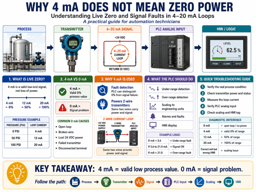
Understanding Live Zero and Signal Faults in 4–20 mA Loops
In industrial instrumentation, one of the most important concepts for automation technicians to understand is this:
In a 4–20 mA signal, 4 mA does not mean the loop is off.
This can confuse new technicians because we often associate “zero” with no signal, no power, or no output. But in a 4–20 mA current loop, the signal does not start at 0 mA. It starts at 4 mA.
That 4 mA is intentional.
It allows the transmitter to represent a valid low process value while still having enough current available to operate, especially in 2-wire loop-powered transmitter circuits. The book Lessons In Industrial Instrumentation explains that a 2-wire loop-powered transmitter uses the same two wires for both power and signal, with the transmitter regulating loop current to represent the process measurement while relying on a remote power source.
The Basic Idea
In a standard 4–20 mA signal:
4 mA  = 0% process value
12 mA = 50% process value
20 mA = 100% process value
But:
0 mA = signal problemThat means 4 mA is a valid signal.
0 mA is not normally a valid process value in a 4–20 mA loop.
What Is “Live Zero”?
A 4–20 mA signal is called a live zero signal.
Live zero means the signal has a live, active current value even when the measured process is at the low end of the range.
Example:
0 PSI = 4 mAThe process value is zero, but the electrical signal is not zero.
This is useful because the PLC can tell the difference between:
| Signal | Meaning |
|---|---|
| 4 mA | Valid low process value |
| 0 mA | Open loop, no power, broken wire, or failed circuit |
This is one reason 4–20 mA became so common in process instrumentation.
Example: Pressure Transmitter
Imagine this transmitter:
PT-101
Range: 0–100 PSI
Output: 4–20 mA
The relationship is:
| Pressure | Signal |
|---|---|
| 0 PSI | 4 mA |
| 25 PSI | 8 mA |
| 50 PSI | 12 mA |
| 75 PSI | 16 mA |
| 100 PSI | 20 mA |
If the technician measures 4 mA, the transmitter may be saying:
The pressure is at 0 PSI.But if the technician measures 0 mA, the transmitter is probably not sending a valid signal.
Possible causes include:
- Lost 24 VDC power
- Broken wire
- Open loop
- Disconnected terminal
- Failed transmitter
- Blown fuse
- Bad analog input connection
Why 4 mA Is Used Instead of 0 mA
There are two major reasons.
1. It Helps Detect Faults
If the signal started at 0 mA, the PLC would have a harder time knowing the difference between:
Process value = 0%and
Signal wire is brokenWith 4–20 mA, the PLC can detect abnormal low-current conditions.
Example:
4.0 mA = valid 0%
0.0 mA = problem
That makes troubleshooting easier and makes the control system more reliable.
2. It Powers 2-Wire Transmitters
Many field transmitters are 2-wire loop-powered devices.
That means the same two wires provide:
Power to the transmitter
AND
Signal back to the PLC
The transmitter needs some minimum current and voltage to stay alive. The book explains that typical 2-wire loop-powered transmitters depend on the minimum current available at the low end of the signal range, and with a typical 24 VDC source and a 250-ohm input resistor, the transmitter still has usable voltage and at least 4 mA available to operate.
So in a 2-wire loop:
4 mA is not “off.”
4 mA is the transmitter operating at the low end of range.
4 mA vs 0 mA
This is the most important table in this post.
| Current | Interpretation |
|---|---|
| 0 mA | Loop is dead, open, unpowered, or failed |
| 4 mA | Valid 0% process value |
| 8 mA | 25% process value |
| 12 mA | 50% process value |
| 16 mA | 75% process value |
| 20 mA | 100% process value |
Example:
For a 0–100 PSI transmitter:
4 mA = 0 PSI
0 mA = signal failure
Those are not the same thing.
What the PLC Sees
The PLC analog input card reads the current signal and converts it to a raw digital value.
Then the PLC logic scales that raw value into engineering units.
Example:
4–20 mA → Analog Input Raw Counts → Scaling → PSIFor a 0–100 PSI transmitter:
4 mA  = 0 PSI
12 mA = 50 PSI
20 mA = 100 PSI
But if the PLC sees something near 0 mA, the logic should not treat that as 0 PSI.
It should treat it as a possible bad signal.
Bad Signal Detection
A professional PLC program should include signal health checks for analog inputs.
Example:
If signal is too low → Under-range or bad signal
If signal is too high → Over-range or bad signal
A common concept is:
Signal below normal range = possible fault
Signal above normal range = possible fault
Some instrumentation standards and devices use diagnostic ranges below 4 mA and above 20 mA to indicate abnormal conditions. The book includes a section on NAMUR signal levels and also covers current loop troubleshooting methods such as measuring loop current, using clamp-on milliamp meters, using test diodes, shunt resistors, voltage measurements, and loop calibrators.
Practical PLC Signal Health Example
For a pressure transmitter:
PT101_Raw_mA
PT101_Pressure_PSI
PT101_Signal_OK
PT101_UnderRange
PT101_OverRange
Example logic concept:
IF PT101_mA < 3.6
THEN PT101_UnderRange = TRUE
IF PT101_mA > 21.0
THEN PT101_OverRange = TRUEIF PT101_mA >= 3.6
AND PT101_mA <= 21.0
THEN PT101_Signal_OK = TRUEThis prevents the PLC from blindly trusting a bad analog value.
Important Technician Rule
A technician should not troubleshoot a 4 mA reading the same way as a 0 mA reading.
If You Measure 4 mA
Ask:
- Is the process actually at the low end of range?
- Is the transmitter ranged correctly?
- Is the process isolation valve open?
- Is the impulse line plugged?
- Is the transmitter seeing the process?
- Is the PLC scaling correct?
If You Measure 0 mA
Ask:
- Is the loop powered?
- Is the fuse good?
- Is there 24 VDC available?
- Is the wire broken?
- Is the transmitter disconnected?
- Is the analog input wired correctly?
- Is the transmitter failed?
These are two very different troubleshooting paths.
Example Problem: HMI Shows 0 PSI
The HMI shows:
Tank Pressure = 0 PSIA new technician may think:
The transmitter must be dead.But that is not always true.
The technician should measure the loop.
Scenario A
Measured signal:
4 mAInterpretation:
The transmitter is sending a valid low-range signal.Possible causes:
- The process may actually be at 0 PSI.
- The isolation valve may be closed.
- The transmitter may not be sensing the process.
- The impulse line may be plugged.
- The transmitter range may be wrong.
Scenario B
Measured signal:
0 mAInterpretation:
The loop is not functioning correctly.Possible causes:
- No loop power
- Broken wire
- Open circuit
- Failed transmitter
- Disconnected terminal
- Bad input circuit
Same HMI reading, different root cause.
That is why measuring the signal matters.
Voltage Drop and Loop Power Problems
A 4–20 mA loop also needs enough voltage to operate correctly.
This is called loop power or loop compliance.
If there is too much resistance in the loop, the transmitter may not have enough voltage left at its terminals, especially when the current rises near 20 mA.
The book gives an important troubleshooting example: excessive loop resistance may allow a transmitter to operate at low current, such as 4 mA, but become unstable near the high end of range when the voltage drop increases. In that situation, a smart transmitter may cycle on and off because its terminal voltage falls below the required minimum.
This is an advanced but very real troubleshooting issue.
The symptom may look like:
Signal stable at low process value
Signal unstable near high process value
HMI value jumps or surges
Transmitter resets or cycles
Possible causes:
- Too much loop resistance
- Bad added resistor
- Long wire run
- Weak power supply
- Corroded terminals
- Incorrect input resistor
- Too many devices in series
250-Ohm Resistor and 1–5 VDC
Some systems use a precision resistor to convert 4–20 mA into a voltage signal.
A very common value is:
250 ohmsUsing Ohm’s Law:
4 mA × 250 Ω = 1 V
20 mA × 250 Ω = 5 V
So:
| Current | Voltage Across 250 Ω |
|---|---|
| 4 mA | 1 V |
| 12 mA | 3 V |
| 20 mA | 5 V |
The book explains that some controllers interpret voltage instead of current, and a precision resistor can convert a 4–20 mA signal into a 1–5 V signal for the controller’s analog-to-digital converter.
This is useful for troubleshooting because a technician can sometimes measure voltage across the resistor and calculate loop current.
Troubleshooting Table
| Measured Value | Possible Meaning | Technician Action |
|---|---|---|
| 0 mA | No current flow | Check power, fuse, wiring, open loop |
| Below 4 mA | Under-range or fault | Check transmitter diagnostics and loop wiring |
| 4 mA | Valid low process value | Verify process and transmitter range |
| 12 mA | 50% of range | Compare with field condition and HMI |
| 20 mA | 100% of range | Verify high process condition |
| Above 20 mA | Over-range or fault | Check transmitter status and scaling |
| Unstable mA | Noise, loose terminal, voltage issue | Check terminals, shield, power, loop resistance |
| Correct mA but wrong HMI | Scaling or tag issue | Check PLC scaling and HMI tag |
Best Practice for Automation Technicians
When working with analog instrumentation, think in layers:
Process condition
→ Transmitter measurement
→ Loop current
→ PLC analog input
→ Scaling
→ HMI display
→ Logic decision
Do not skip straight to replacing the transmitter.
The best technician asks:
What is the process doing?
What is the instrument measuring?
What current is the loop sending?
What is the PLC reading?
What is the logic doing with that value?
PLC Programming Best Practice
For each important analog instrument, create separate tags for:
Raw Input
Scaled Value
Signal OK
Under-range Fault
Over-range Fault
High Alarm
Low Alarm
High-High Fault
HMI Display Value
Example:
AI_PT101_Raw
AI_PT101_mA
AI_PT101_PSI
AI_PT101_Signal_OK
AI_PT101_UnderRange
AI_PT101_OverRange
PT101_High_Alarm
PT101_HighHigh_Fault
This structure makes troubleshooting much easier from the PLC and HMI.
Key Takeaway
The most important idea is simple:
4 mA = valid low process value
0 mA = signal problem
A 4–20 mA loop uses a live zero so the control system can tell the difference between a real low reading and a failed signal.
For automation technicians, this is a must-know concept.
Final Thoughts
Understanding 4 mA versus 0 mA is one of the foundations of analog instrumentation troubleshooting.
When the HMI shows a low process value, do not guess. Measure the loop current.
If the loop is at 4 mA, the transmitter may be alive and reporting a valid low value.
If the loop is at 0 mA, the technician should start looking for power, wiring, open circuit, or device failure.
A professional troubleshooting mindset is:
Follow the signal before replacing the device.