4. Understanding 4–20 mA Current Loops
A Practical Guide for Automation Technicians
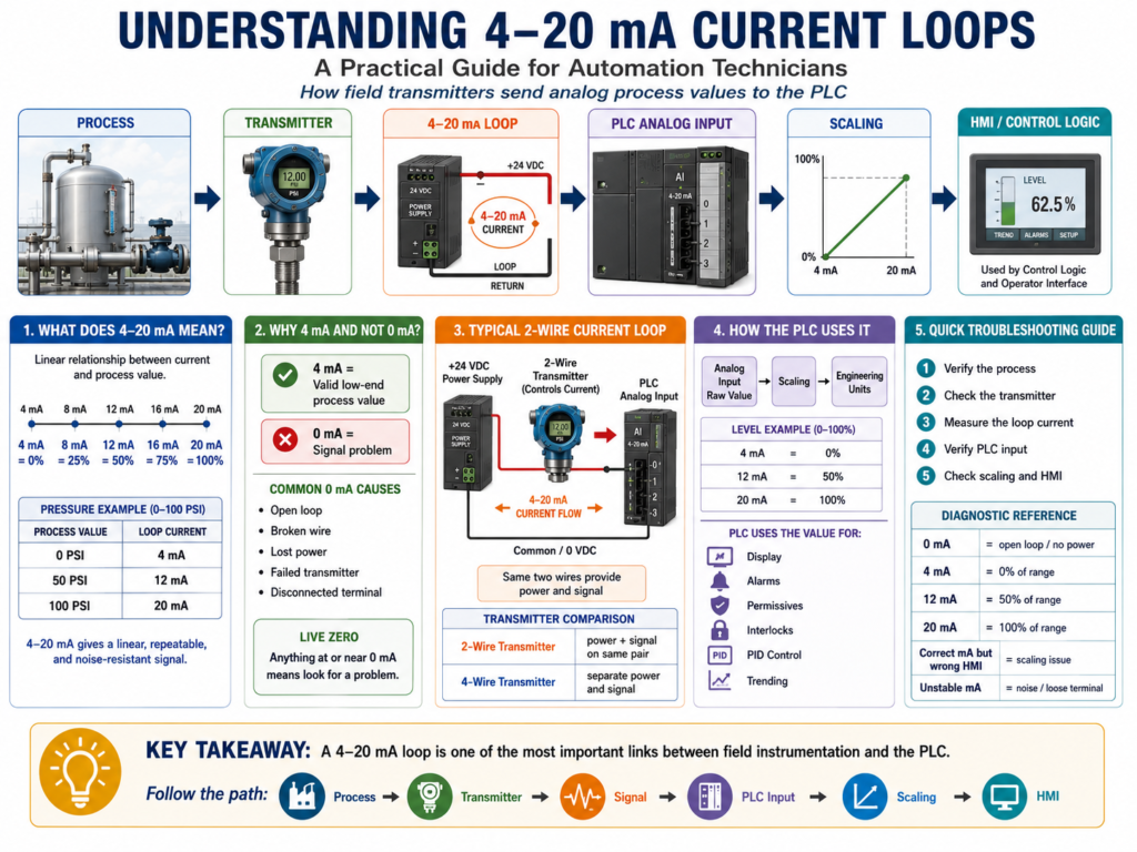
One of the most important signals in industrial instrumentation is the 4–20 mA current loop.
If you work with pressure transmitters, level transmitters, flowmeters, temperature transmitters, pH transmitters, control valves, I/P transducers, or PLC analog input cards, you will see 4–20 mA signals many times.
For automation technicians, this is a signal that must be understood very well because it connects the field instrument to the PLC, controller, or control system.
In simple terms:
A 4–20 mA signal is an analog current signal used to represent a process value.
Example:
0 PSI   = 4 mA
50 PSI  = 12 mA
100 PSI = 20 mA
The book Lessons In Industrial Instrumentation explains 4–20 mA analog current signals, how they relate to process variables, how 2-wire loop-powered transmitters work, and how technicians can troubleshoot current loops using milliammeters, clamp-on milliamp meters, test diodes, shunt resistors, and voltage measurements.
Why 4–20 mA Is So Common
The 4–20 mA signal is widely used because it is practical, reliable, and easy to troubleshoot.
A transmitter measures a real process condition and converts it into current.
Example:
Pressure Transmitter → 4–20 mA Signal → PLC Analog Input → Scaled PSIThis signal is used for many process variables:
| Process Variable | Common Instrument |
|---|---|
| Pressure | Pressure transmitter |
| Level | Level transmitter |
| Flow | Flow transmitter |
| Temperature | Temperature transmitter |
| pH | pH transmitter |
| Weight | Weight transmitter |
| Valve Position | Position transmitter |
| Control Output | I/P transducer or valve positioner |
The Basic 4–20 mA Relationship
A 4–20 mA signal represents a process range.
The most common interpretation is:
| Current Signal | Percent of Range |
|---|---|
| 4 mA | 0% |
| 8 mA | 25% |
| 12 mA | 50% |
| 16 mA | 75% |
| 20 mA | 100% |
Example:
A pressure transmitter is ranged from 0 to 100 PSI.
| Pressure | Current |
|---|---|
| 0 PSI | 4 mA |
| 25 PSI | 8 mA |
| 50 PSI | 12 mA |
| 75 PSI | 16 mA |
| 100 PSI | 20 mA |
This means that if a technician measures 12 mA, the process should be around 50% of range.
For this example:
12 mA = 50 PSIImportant Concept: 4 mA Is Not Zero Current
This is one of the most important things to understand.
In a 4–20 mA signal:
4 mA = 0% process value
0 mA = bad signal condition
That means 4 mA does not mean the loop is dead.
It usually means the process is at the low end of the calibrated range.
Example:
4 mA = 0 PSIBut:
0 mA = open circuit, lost power, broken wire, failed transmitter, or disconnected loopThis is called a live zero signal.
A live zero helps the control system distinguish between a valid low reading and a failed signal.
Why the Signal Starts at 4 mA
The signal starts at 4 mA instead of 0 mA for two big reasons:
1. Fault Detection
If the PLC sees 0 mA, that is not a valid process reading. It usually means something is wrong.
Possible causes:
- Broken wire
- Open loop
- Lost 24 VDC supply
- Failed transmitter
- Disconnected terminal
- Blown fuse
- Bad analog input circuit
2. Loop-Powered Transmitters
Many transmitters are 2-wire loop-powered transmitters.
This means the same two wires provide:
Power for the transmitter
AND
Signal back to the control system
In a 2-wire loop, the transmitter uses the loop current to operate while regulating that same current to represent the process measurement. The book explains that a loop-powered transmitter relies on a remote power source and acts like a current regulator in the series loop.
Basic 2-Wire Current Loop
A basic 2-wire 4–20 mA loop has:
24 VDC Power Supply
+ Transmitter
+ PLC Analog Input
+ Wiring
A simplified path looks like this:
+24 VDC → Transmitter → PLC Analog Input → 0 VDC/CommonThe transmitter controls how much current flows in the loop.
Example:
| Process Condition | Loop Current |
|---|---|
| Low end of range | 4 mA |
| Mid range | 12 mA |
| High end of range | 20 mA |
The PLC analog input reads that current and converts it into a raw digital value. Then the PLC logic scales that raw value into engineering units.
4–20 mA → Raw Counts → Scaling → PSI, GPM, °F, %, Gallons2-Wire vs 4-Wire Transmitters
Not every transmitter is wired the same way.
2-Wire Transmitter
A 2-wire transmitter uses the same two wires for power and signal.
Two wires = power + 4–20 mA signalCommon with:
- Pressure transmitters
- Level transmitters
- Temperature transmitters
- Flow transmitters
- Smart HART transmitters
Advantages:
- Less wiring
- Common in process instrumentation
- Easy to integrate with analog input cards
- Works well over long cable runs
4-Wire Transmitter
A 4-wire transmitter usually has separate wires for power and signal.
Two wires = power
Two wires = signal
Common with:
- Some flowmeters
- Analyzers
- Powered instruments
- Devices with displays, heaters, or advanced electronics
The book notes that 4-wire transmitter systems require additional conductors, which means larger cables, more terminal blocks, and more installation cost compared with 2-wire loops.
Current Loop vs Voltage Signal
A 4–20 mA signal is a current signal, not a voltage signal.
That matters.
With current loops, the same current flows through all devices in the series loop.
This makes current loops useful in industrial environments because they are generally more tolerant of voltage drops across long wire runs than voltage-based signals like 0–10 VDC.
4–20 mA Current Signal
Good for:
- Long cable distances
- Industrial process instrumentation
- Noise-prone environments
- Fault detection with live zero
- PLC analog inputs
0–10 VDC Voltage Signal
Common in:
- Drives
- HVAC controls
- Shorter cable runs
- Some machine controls
- Smaller automation systems
Voltage signals can be affected more easily by voltage drop and electrical noise.
How the PLC Reads 4–20 mA
The PLC analog input card does not automatically know the process value.
It reads the electrical signal and converts it to a digital number.
Example:
4 mA  → Raw minimum
20 mA → Raw maximum
Then the PLC scales the raw value into engineering units.
Example:
Raw Analog Input → Scale Instruction → Tank_Level_PercentFor a level transmitter:
4 mA  = 0%
20 mA = 100%
For a pressure transmitter:
4 mA  = 0 PSI
20 mA = 100 PSI
For a temperature transmitter:
4 mA  = 32 °F
20 mA = 212 °F
The same 4–20 mA signal can represent many different things. The difference is the instrument range and the PLC scaling.
LRV and URV
Two common terms in instrumentation are:
| Term | Meaning |
|---|---|
| LRV | Lower Range Value |
| URV | Upper Range Value |
Example:
LRV = 0 PSI
URV = 100 PSI
That means:
4 mA  = LRV = 0 PSI
20 mA = URV = 100 PSI
Another example:
LRV = 32 °F
URV = 212 °F
That means:
4 mA  = 32 °F
20 mA = 212 °F
This is very important when troubleshooting HMI values.
If the transmitter range and PLC scaling do not match, the HMI value will be wrong even if the transmitter and wiring are good.
Example: Level Transmitter
Instrument:
LT-101
Range: 0–100%
Output: 4–20 mA
PLC Tag: AI_Tank_Level_Pct
Expected values:
| Tank Level | Current |
|---|---|
| 0% | 4 mA |
| 25% | 8 mA |
| 50% | 12 mA |
| 75% | 16 mA |
| 100% | 20 mA |
PLC usage:
IF AI_Tank_Level_Pct < 15%
THEN Low_Level_Alarm = TRUE
IF AI_Tank_Level_Pct > 90%
THEN High_Level_Alarm = TRUEIF AI_Tank_Level_Pct > 20%
THEN Pump_Start_Permissive = TRUEThis shows how a 4–20 mA signal becomes useful inside PLC logic.
Example: Pressure Transmitter
Instrument:
PT-201
Range: 0–150 PSI
Output: 4–20 mA
PLC Tag: AI_Discharge_Pressure_PSI
Expected values:
| Pressure | Current |
|---|---|
| 0 PSI | 4 mA |
| 37.5 PSI | 8 mA |
| 75 PSI | 12 mA |
| 112.5 PSI | 16 mA |
| 150 PSI | 20 mA |
PLC usage:
IF AI_Discharge_Pressure_PSI > 125 PSI
THEN High_Pressure_Alarm = TRUE
IF AI_Discharge_Pressure_PSI > 140 PSI
THEN High_High_Pressure_Fault = TRUEMeasuring a 4–20 mA Signal
A technician may need to measure loop current when the HMI value does not match the field condition.
There are several ways to measure a 4–20 mA loop.
1. Standard Multimeter in Series
A normal multimeter can measure milliamps, but it must be connected in series with the loop.
That means the loop must be opened.
This can interrupt the process signal.
The book warns that breaking the loop can temporarily force the signal to 0 mA, which may affect the controller, trigger alarms, or upset the process. It recommends proper preparation before interrupting a live loop, such as notifying personnel, placing a controller in manual mode, or considering process alarms and shutdown functions.
2. Clamp-On Milliamp Meter
A clamp-on milliamp meter measures the signal without opening the circuit.
This is safer and faster when available.
The book explains that Hall-effect clamp-on milliammeters can measure small DC loop currents non-intrusively by clamping around the wire, avoiding the need to break the circuit.
3. Test Terminals
Some transmitters have dedicated TEST terminals.
These allow a technician to measure loop current without disconnecting the main loop wires.
The book explains that some process transmitters include test points specifically for measuring the 4–20 mA current signal without undoing wiring connections.
4. Shunt Resistor
A precision resistor can be placed in the loop. The technician measures voltage across the resistor and calculates current using Ohm’s Law.
V = I × RThe book explains that shunt resistors allow current measurement by measuring voltage across a known resistance, then applying Ohm’s Law.
Quick 4–20 mA Troubleshooting Table
| Measured Signal | Possible Meaning |
|---|---|
| 0 mA | Open loop, no power, broken wire, failed transmitter |
| Less than 4 mA | Under-range, fault condition, wiring issue |
| 4 mA | Valid 0% process value |
| 12 mA | Valid 50% process value |
| 20 mA | Valid 100% process value |
| Greater than 20 mA | Over-range, fault condition, transmitter issue |
| Unstable mA | Noise, loose terminal, bad shield, failing transmitter |
| Correct mA but wrong HMI value | Scaling or HMI tag issue |
Professional Troubleshooting Method
When a 4–20 mA reading looks wrong, follow the signal path.
Step 1 — Verify the Process
Ask:
Is the real process condition actually what the HMI says?Use:
- Local gauge
- Sight glass
- Manual reading
- Field display
- Operator observation
- Known process condition
Step 2 — Verify the Transmitter
Check:
- Is the transmitter powered?
- Is the display alive?
- Is the range correct?
- Is the process connection open?
- Is an isolation valve closed?
- Is the impulse line plugged?
- Is the sensor damaged?
- Is the transmitter in alarm mode?
Step 3 — Measure the Loop Signal
Check the actual mA value.
Example:
Measured loop current = 12 mAFor a 0–100 PSI transmitter:
12 mA should equal about 50 PSIIf the field pressure is 50 PSI and the signal is 12 mA, the transmitter is probably doing its job.
Step 4 — Verify the PLC Analog Input
Check:
- Analog input LED/status
- Raw input value
- Channel configuration
- Wiring polarity
- Input common/reference
- Card fault
- Module diagnostics
Step 5 — Verify Scaling
Ask:
Does 4 mA equal the correct LRV?
Does 20 mA equal the correct URV?
Example problem:
Transmitter range: 0–150 PSI
PLC scaling: 0–100 PSI
Result:
HMI value will be wrongPLC Logic Best Practices
For industrial PLC programs, separate analog handling into clear steps.
1. Raw Input
AI_PT201_Raw2. Scaled Engineering Value
AI_PT201_Pressure_PSI3. Signal Health
AI_PT201_Signal_OK
AI_PT201_UnderRange
AI_PT201_OverRange
4. Alarm Logic
PT201_High_Alarm
PT201_HighHigh_Fault
PT201_Low_Alarm
5. HMI Display
PT201_HMI_Display_PSIThis makes troubleshooting easier because the technician can see where the problem is.
Technician Example: HMI Shows 0 PSI
Problem:
HMI shows 0 PSI
Field gauge shows 50 PSI
Possible causes:
| Area | Possible Problem |
|---|---|
| Process | Gauge may be wrong or isolated |
| Transmitter | No power, failed sensor, wrong range |
| Loop | Open wire, loose terminal, bad fuse |
| PLC Input | Bad channel, wrong configuration |
| Scaling | Wrong raw range or engineering range |
| HMI | Wrong tag or display format |
Professional check:
- Verify actual pressure.
- Check transmitter display.
- Measure loop current.
- Confirm PLC raw input.
- Confirm scaling.
- Confirm HMI tag.
Key Takeaway
A 4–20 mA current loop is one of the most important links between field instrumentation and the PLC.
Remember:
4 mA  = 0% process value
12 mA = 50% process value
20 mA = 100% process value
0 mA  = signal problem
The technician’s job is to follow the path:
Process → Transmitter → 4–20 mA Loop → PLC Analog Input → Scaling → HMI Display → LogicIf you understand this path, you can troubleshoot most analog instrumentation problems more professionally.
Final Thoughts
For automation technicians, 4–20 mA is not just a theory topic. It is a daily troubleshooting skill.
When a pressure, level, flow, or temperature value looks wrong on the HMI, do not guess. Measure the signal, verify the transmitter, check the PLC raw value, and confirm the scaling.
A strong technician understands that the PLC is only as good as the signal it receives.