3. HMI Communications: FactoryTalk Linx, Data Servers, and OPC
Understanding How the HMI Talks to the PLC
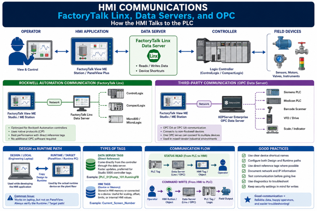
In an industrial HMI system, the screen is only useful if it can communicate with the controller.
The HMI needs to read machine status from the PLC and write operator commands back to the PLC. Without communication, the HMI becomes just a static picture.
A simple communication path looks like this:
Operator
   ↓
HMI Screen
   ↓
HMI Tag or Direct Reference
   ↓
FactoryTalk Linx or OPC Data Server
   ↓
PLC / Controller
   ↓
Field Devices
When communication is working properly, the operator sees live values, alarms update correctly, buttons write commands, trends move, and diagnostics show valid activity.
When communication fails, the HMI may show stale values, question marks, diagnostic messages, broken tag references, inactive buttons, or communication errors.
What Is HMI Communication?
HMI communication is the process of exchanging data between the HMI application and the control system.
The HMI usually needs to:
Read PLC status bits
Read analog process values
Read alarm conditions
Read motor feedback
Read valve position feedback
Write operator commands
Write setpoints
Write recipe values
Write reset commands
Write mode selections
For example, if the operator sees a pump running on the HMI, that running status usually comes from a PLC tag or feedback bit.
Motor Starter Feedback
   ↓
PLC Input / PLC Tag
   ↓
FactoryTalk Linx
   ↓
HMI Graphic Object
   ↓
Operator sees: Pump Running
If the operator presses Start Pump, the command travels in the opposite direction:
Operator presses Start
   ↓
HMI Button
   ↓
FactoryTalk Linx
   ↓
PLC Command Tag
   ↓
PLC Logic checks permissives
   ↓
PLC turns on output
The HMI does not “magically know” what is happening in the machine. It depends on a communication layer.
What Is a Data Server?
In modern FactoryTalk View ME systems, the communication layer is handled by a data server.
A data server provides access to devices on the network. It allows the HMI application to browse, read, and write values from controllers and other automation devices. FactoryTalk View ME supports Rockwell Automation device servers and OPC data servers.
A simple way to think about it:
The data server is the bridge between the HMI and the controller.The HMI does not directly connect every button and display object to the PLC by itself. The data server handles the communication path.
FactoryTalk Linx: The Rockwell Communication Bridge
For Rockwell Automation controllers, FactoryTalk Linx is the recommended data server.
FactoryTalk Linx is used to connect FactoryTalk View ME applications to Rockwell Automation devices and networks. It allows the HMI application to browse controller tags, read values, and write values.
Typical Rockwell communication path:
FactoryTalk View ME
   ↓
FactoryTalk Linx Data Server
   ↓
Device Shortcut
   ↓
ControlLogix / CompactLogix Controller
FactoryTalk View ME documentation identifies FactoryTalk Linx as the recommended data server for Rockwell Automation devices and networks. It also states that FactoryTalk Linx does not require activation or licensing and can be installed as often as needed in any application.
What Is a Device Shortcut?
A device shortcut is a logical name that points to a controller.
Instead of writing the full controller path everywhere in the HMI application, FactoryTalk View uses a shortcut.
Example:
[PLC_01]Pump_101.RunningFBIn this example:
[PLC_01] = Device shortcut
Pump_101.RunningFB = Controller tag
The shortcut tells FactoryTalk Linx which controller to use.
A good device shortcut name should be clear and practical:
Line1_PLC
Mixer_PLC
Packaging_PLC
TankFarm_PLC
PLC_01
Avoid unclear shortcut names like:
Shortcut1
Test
PLC
NewShortcut
A bad shortcut name makes troubleshooting harder, especially when a plant has multiple controllers.
Design Path vs Runtime Path
This is one of the most important communication concepts in FactoryTalk View ME.
FactoryTalk Linx communication setup has two important paths:
| Path | Used By | Purpose |
|---|---|---|
| Design / Local | Engineering laptop or development PC | Used while building and testing the HMI |
| Runtime / Target | PanelView Plus or runtime computer | Used when the HMI runs on the machine |
The Design path tells FactoryTalk View Studio where to find the controller while you are developing.
The Runtime path tells the PanelView Plus or runtime device where to find the controller after the .MER file is running on the plant floor.
FactoryTalk View ME documentation explains that the Design (Local) tab is used to establish where tags and addresses are found during editing, while the Runtime (Target) tab identifies the connection from the runtime terminal or computer to the controller or other data server. If both paths are the same, the configuration can be copied from Design to Runtime.
Common Field Problem
One of the most common HMI communication issues is:
“It works on my laptop, but it does not work on the PanelView.”This usually means the HMI worked in the Design / Local path, but the Runtime / Target path was not configured correctly.
Possible causes:
Runtime shortcut points to the wrong PLC
Runtime shortcut was not copied from Design
PanelView has a different network path
Wrong IP address
Controller not reachable from the PanelView
PanelView and PLC are on different networks
Downloaded old .MER file
Wrong communication driver
Wrong device shortcut name
This is why technicians must always verify both paths.
OPC: Open Communication Between Different Vendors
Not every plant uses only Rockwell Automation devices.
You may have:
Siemens PLCs
Modicon controllers
Barcode scanners
Power meters
Scale systems
Temperature controllers
Third-party drives
Analyzers
Robots
This is where OPC becomes important.
OPC is a communication standard that allows software from different vendors to exchange industrial data.
A simple OPC architecture looks like this:
FactoryTalk View ME
   ↓
OPC Data Server
   ↓
Third-Party Device
For FactoryTalk View ME, KEPServer Enterprise is commonly used as an OPC data server for third-party devices. The manual identifies KEPServer Enterprise as an OPC Data Access v2.05a server and notes that it is used to communicate with non-Rockwell Automation devices such as Siemens or Modicon controllers.
FactoryTalk Linx vs OPC Data Server
Both FactoryTalk Linx and OPC data servers move data, but they are commonly used in different situations.
| Communication Method | Common Use |
|---|---|
| FactoryTalk Linx | Rockwell Automation controllers and networks |
| KEPServer Enterprise / OPC | Third-party devices such as Siemens or Modicon |
| Other OPC servers | Vendor-specific or multi-vendor systems |
Example with Rockwell controller:
PanelView Plus
   ↓
FactoryTalk View ME Station
   ↓
FactoryTalk Linx
   ↓
CompactLogix PLC
Example with third-party controller:
PanelView Plus or PC Runtime
   ↓
FactoryTalk View ME Station
   ↓
KEPServer Enterprise
   ↓
Siemens or Modicon Controller
The important concept is simple:
The HMI needs a data server that understands the device.OPC DA vs OPC UA
You will often hear two OPC terms:
OPC DA
OPC UA
OPC DA
OPC DA means OPC Data Access.
It is an older OPC technology commonly used in legacy Windows-based industrial systems. FactoryTalk View ME documentation specifically mentions OPC Data Access v2.05a support.
OPC UA
OPC UA means OPC Unified Architecture.
It is newer, more secure, and more platform-independent. Many modern systems, including modern SCADA platforms, use OPC UA heavily.
For this post, the main concept is:
OPC allows different industrial systems to exchange data using a common standard.What Are Data Server Tags?
A data server tag is a tag that comes directly from a data server, such as FactoryTalk Linx or an OPC server.
Example:
[Line1_PLC]Pump_101.RunningFB
[Line1_PLC]Tank_201.Level_PV
[Line1_PLC]Valve_305.OpenFB
In these examples:
[Line1_PLC] = Device shortcut
Pump_101.RunningFB = Controller tag
FactoryTalk View ME describes data server tags as tags provided through data servers such as FactoryTalk Linx or KEPServer Enterprise. These can include Studio 5000 processor tags and tags from other OPC-compliant devices.
Direct References: The Modern Preferred Method
In many modern FactoryTalk View ME applications, direct references are preferred.
Instead of creating every tag inside the HMI tag database, the HMI can directly reference controller tags through FactoryTalk Linx.
Example:
[PLC_01]Mixer_01.StartCmd
[PLC_01]Mixer_01.RunningFB
[PLC_01]Mixer_01.Faulted
FactoryTalk View ME documentation states that direct reference tags usually update faster than HMI tags, and recommends using direct references where possible for the best system performance.
This is very important for technicians because modern HMI projects may not have a large traditional HMI tag database. Instead, many graphic objects may reference controller tags directly.
HMI Tags Still Have a Purpose
Even though direct references are often preferred, HMI tags are still useful.
Use HMI tags when you need:
Internal HMI memory
Temporary display values
Scaling
Offset
Minimum write limits
Maximum write limits
Values that do not exist in the PLC
Special HMI-only logic
FactoryTalk View ME allows HMI tags to use either memory or a device as the data source. A device tag receives data from an external source, while a memory tag stores values in FactoryTalk View internal memory.
Example HMI memory tag:
Current_Screen_Number
Selected_Recipe_Index
Operator_Message_Number
Maintenance_Mode_Selected
Online Tags vs Offline Tags
FactoryTalk View ME can browse tags online or offline.
Online Tags
Online tags are available when the development computer is connected to the controller.
Example:
FactoryTalk View Studio → FactoryTalk Linx → Online ControllerOffline Tags
Offline tags are available from an offline controller project file, such as an .ACD file.
Example:
FactoryTalk View Studio → Offline ACD File → Controller Tag ListFactoryTalk View ME documentation explains that each FactoryTalk Linx device shortcut can show both Online and Offline folders in the Tag Browser. The Offline folder can be used to browse tags from an RSLogix or Studio 5000 .ACD file, while the Online folder is used when connected to the controller.
This is helpful when building screens before the machine is online.
Communication Setup Workflow
A typical FactoryTalk View ME communication setup looks like this:
1. Identify the PLC or controller
2. Confirm the controller IP address or network path
3. Open FactoryTalk Linx Communication Setup
4. Create or verify the device shortcut
5. Set the Design / Local path
6. Set the Runtime / Target path
7. Test tag browsing
8. Assign tags to graphic objects
9. Create the .MER runtime file
10. Transfer the .MER to the PanelView Plus or runtime computer
11. Test communication at runtime
FactoryTalk View ME documentation explains that FactoryTalk Linx Communication Setup is used to add drivers, add devices, set driver and device properties, and set up device shortcuts.
What Can Go Wrong?
HMI communication problems are common in the field.
Here are some typical symptoms:
| Symptom | Possible Cause |
|---|---|
| HMI shows question marks or blank values | Tag not found, communication path issue, bad shortcut |
| HMI works on laptop but not PanelView | Runtime path not configured correctly |
| Button does nothing | Wrong tag, security issue, PLC interlock, bad write path |
| Tags browse online but fail at runtime | Design path works, Runtime path does not |
| HMI cannot see controller | Network issue, wrong IP, wrong subnet, controller offline |
| Trend is flat | Tag not updating, communication issue, logging issue |
| Alarm does not trigger | Wrong alarm tag, wrong trigger, value not reaching HMI |
| Slow display loading | Too many tags, heavy graphics, slow controller response |
Communication Troubleshooting Path
When the HMI is not communicating, follow a structured path.
1. Verify the PLC is powered and running
2. Verify the PanelView or runtime computer has network connectivity
3. Ping the PLC from the HMI network if possible
4. Verify IP address, subnet, and gateway
5. Verify FactoryTalk Linx can see the controller
6. Verify the device shortcut points to the correct controller
7. Verify both Design and Runtime paths
8. Browse tags online
9. Test a simple numeric display or indicator
10. Check FactoryTalk Diagnostics
11. Confirm the correct .MER file is running
12. Check security if writes are not working
FactoryTalk Diagnostics can help troubleshoot system activity such as tag reads and writes, macros, communication problems, and problems opening displays.
Technician Example: Pump Running Status
Let’s follow one simple status signal.
Motor feedback contact closes
   ↓
PLC input turns ON
   ↓
PLC tag Pump_101.RunningFB = 1
   ↓
FactoryTalk Linx reads the tag
   ↓
HMI motor object changes color
   ↓
Operator sees Pump 101 Running
If the motor is running in the field but the HMI does not show it, check:
Is the feedback wired correctly?
Does the PLC input turn ON?
Does the PLC tag turn ON?
Can FactoryTalk Linx read the tag?
Is the HMI object connected to the correct tag?
Is the correct .MER running?
Is the Runtime path correct?
Do not start by editing the graphic. First, prove the data path.
Technician Example: Start Command
Now follow a command.
Operator presses Start
   ↓
HMI writes Pump_101.StartCmd
   ↓
FactoryTalk Linx sends the write to the PLC
   ↓
PLC logic sees the command
   ↓
PLC checks permissives
   ↓
PLC energizes output
If the button does nothing, check:
Is the button connected to the correct tag?
Is the tag write allowed?
Is the user authorized?
Is the Runtime shortcut correct?
Is the PLC seeing the command?
Is the PLC blocking the start due to an interlock?
Is there an active fault?
Remember:
The HMI requests.
The PLC decides.
Best Practices for HMI Communication
Use Clear Shortcut Names
Good:
Line1_PLC
Mixer_PLC
Packaging_PLC
TankFarm_PLC
Poor:
Shortcut1
NewShortcut
TestPLC
PLC
Always Configure Runtime Path
Do not only test the Design path. Always verify the Runtime path before downloading the application.
A good habit:
Design path configured
Runtime path configured
Shortcut verified
Tags browse correctly
.MER created
.MER downloaded
Runtime tested
Use Direct References Where Possible
For modern Logix-based systems, direct references usually provide better performance and reduce duplicated tag maintenance.
Example:
[Line1_PLC]Motor_101.RunningFBUse HMI tags when you specifically need memory, scaling, offset, or HMI-only behavior.
Keep Network Information Documented
Document:
PLC name
PLC IP address
PanelView IP address
Subnet mask
Gateway
Device shortcut name
Runtime file name
FactoryTalk View version
Controller program name
This information saves time during troubleshooting.
Use Diagnostics
Do not ignore diagnostic messages.
FactoryTalk Diagnostics can point you toward:
Bad tag reference
Communication timeout
Display open problem
Macro issue
Tag write issue
Security-related issue
Runtime error
Diagnostics are part of professional troubleshooting.
Legacy Note: RSLinx and DDE
Older Rockwell HMI systems such as RSView32 commonly used RSLinx, OPC, and DDE.
DDE is a legacy Windows data exchange method. It can help explain historical HMI communication, but it is not the main focus for modern machine-level HMI design.
The modern FactoryTalk View ME approach is centered around:
FactoryTalk Linx
Data servers
Device shortcuts
Direct reference tags
OPC data servers
Runtime paths
.MER deployment
FactoryTalk Diagnostics
This is the language a technician is more likely to see today when working with PanelView Plus and FactoryTalk View ME systems.
Final Thoughts
HMI communication is the foundation that makes the operator interface useful.
The screen, buttons, alarms, and trends only work if the HMI can reliably exchange data with the controller.
In modern Rockwell Automation systems, FactoryTalk View ME uses FactoryTalk Linx as the recommended data server for Rockwell controllers and OPC data servers, such as KEPServer Enterprise, for third-party devices.
A technician who understands data servers, device shortcuts, direct references, Design vs Runtime paths, and diagnostics will be much stronger when troubleshooting HMI problems in the field.
Technician Takeaway
The HMI screen shows the data.
The data server moves the data.
The device shortcut points to the controller.
The Runtime path must work on the actual PanelView.
The PLC still makes the final control decision.
When troubleshooting communication, always follow the data path:
Field Device → PLC Tag → Data Server → HMI Tag/Object → Operator ScreenAnd for commands:
Operator Button → HMI Tag/Object → Data Server → PLC Logic → Field Output