2. HMI Architecture: PLC, Driver, Tags, and Screens
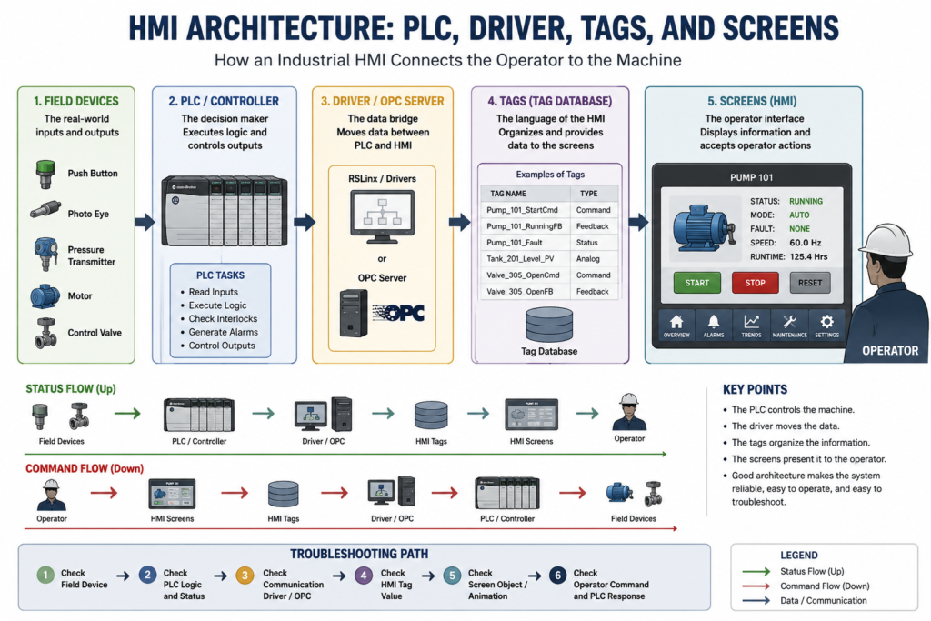
Understanding How an Industrial HMI Connects the Operator to the Machine
In the previous post, we explained what an industrial HMI is and why it is important in automation. Now we are going one level deeper: HMI architecture.
An HMI is not just a screen with buttons and graphics. Behind every HMI screen there is a structured system that allows data to move from the machine to the operator and from the operator back to the control system.
A simple modern HMI architecture can be understood like this:
Field Devices
   ↓
PLC / Controller
   ↓
FactoryTalk Linx or OPC Data Server
   ↓
Data Server Tags / HMI Tags
   ↓
Graphic Displays, Alarms, Trends, and Diagnostics
   ↓
FactoryTalk View ME Station / PanelView Plus
   ↓
Operator
This architecture is important because when something does not work on the HMI, the problem may not be the screen itself. The issue could be in the field device, PLC logic, communication path, data server, tag reference, graphic object, runtime file, or operator security level.
FactoryTalk View ME applications are built around this same idea. A FactoryTalk View ME application consists of one or more data servers and an HMI project, also called an HMI server. The data servers provide communication for the project, while the HMI project contains graphic displays, alarm information, user information, and other settings.
The Big Picture
An industrial HMI system usually has five major layers:
| Layer | Purpose |
|---|---|
| Field Devices | Real-world sensors and outputs |
| PLC / Controller | Executes control logic |
| Data Server / Driver | Moves data between PLC and HMI |
| Tags | Organize the data used by the HMI |
| Screens / Runtime | Display information and accept operator interaction |
Each layer has a job. If one layer is not configured correctly, the HMI may display wrong values, show communication errors, fail to update, or send commands to the wrong place.
In modern Rockwell systems, FactoryTalk View Studio is used to build and test the HMI application, while FactoryTalk View ME Station runs the application on devices such as PanelView Plus terminals, MobileView terminals, Rockwell Automation industrial computers, or other industrial PCs.
1. Field Devices: The Real-World Inputs and Outputs
The field devices are the physical equipment connected to the control system.
Examples include:
Push buttons
Limit switches
Photo eyes
Proximity sensors
Pressure transmitters
Temperature sensors
Flow meters
Motors
Valves
Solenoids
VFDs
Stack lights
Barcode scanners
These devices normally do not communicate directly with the HMI. They are wired or networked to the PLC, remote I/O, drive, or controller system.
For example:
Photo Eye → PLC Input
Motor Starter → PLC Output
Level Transmitter → Analog Input Module
Control Valve → Analog Output or Digital Output
VFD Status → PLC or Networked Drive Tag
The HMI only shows what the control system makes available through data server tags, HMI tags, or direct references.
2. PLC / Controller: The Decision Maker
The PLC is the controller that executes the machine logic.
The PLC reads inputs, processes logic, and controls outputs. It handles:
Permissives
Interlocks
Start/stop logic
Alarms
Faults
Timers
Counters
Sequencing
Analog scaling
Motor control
Valve control
Machine states
Safety-related status monitoring
A very important concept is:
The HMI requests. The PLC decides.
For example, when an operator presses a Start Pump button on the HMI, the HMI should not be considered the final authority. The HMI usually writes a command bit or command value to the PLC. Then the PLC decides whether the pump is allowed to start.
The PLC may check:
Is the E-stop OK?
Is the overload OK?
Is the pump in Auto?
Is there a low-level permissive?
Is the discharge valve open?
Is there an active fault?
Is the motor starter feedback healthy?
Only after those conditions are satisfied should the PLC energize the output.
This keeps the control system safer, more predictable, and easier to troubleshoot.
3. Data Server / Driver: The Communication Bridge
In older HMI systems, technicians often used the word driver to describe the communication layer. In modern FactoryTalk View ME applications, the more accurate term is usually data server.
A data server provides access to devices on the network. It allows the HMI application to browse, read, and write values from controllers and other automation devices. FactoryTalk View ME supports Rockwell Automation device servers and OPC data servers.
In Rockwell Automation systems:
FactoryTalk View ME → FactoryTalk Linx → Logix ControllerFor third-party devices:
FactoryTalk View ME → KEPServer Enterprise / OPC Server → Third-Party ControllerFactoryTalk View ME documentation identifies FactoryTalk Linx as the recommended data server for Rockwell Automation devices and networks. It also explains that KEPServer Enterprise can be used as an OPC data server to communicate with non-Rockwell Automation devices such as Siemens or Modicon controllers.
Direct Driver vs OPC Data Server
There are two common communication ideas to understand.
Direct / Native Rockwell Communication
This is common when the HMI and PLC are both part of the Rockwell Automation ecosystem.
Example:
PanelView Plus
   ↓
FactoryTalk View ME Station
   ↓
FactoryTalk Linx
   ↓
ControlLogix / CompactLogix Controller
FactoryTalk Linx handles the connection between the HMI application and the Rockwell controller.
OPC Data Server
OPC acts like a standard industrial data bridge. It allows software from different vendors to exchange data.
Example:
FactoryTalk View ME
   ↓
OPC Data Server
   ↓
Third-Party PLC or Device
In FactoryTalk View ME, KEPServer Enterprise is commonly used when the HMI must communicate with third-party devices. The manual notes that KEPServer Enterprise is an OPC DA v2.05a compliant server and is used for non-Rockwell Automation devices.
4. Design Path vs Runtime Path
This is one of the most important modern FactoryTalk View ME concepts for technicians.
In FactoryTalk Linx Communication Setup, there are two important paths:
| Path | Purpose |
|---|---|
| Design / Local | Used while developing the HMI application on the engineering computer |
| Runtime / Target | Used by the actual runtime terminal, such as a PanelView Plus |
The Design (Local) tab tells FactoryTalk View Studio where to find tags while you are building and testing the application.
The Runtime (Target) tab tells the PanelView Plus or runtime computer how to reach the controller when the application is running on the machine.
FactoryTalk View ME documentation explains that the Design tab is used for tag/address locations during editing, while the Runtime tab identifies the connection from the runtime computer or terminal to the controller or data server. If the paths are the same, the configuration can be copied from Design to Runtime.
This matters because a common field problem is:
The HMI works on the development laptop,
but it does not work after downloading the .MER to the PanelView.
A very common cause is that the Runtime (Target) path or device shortcut is not configured correctly.
5. Tags: The Language of the HMI
Tags are one of the most important parts of HMI architecture.
A tag is a logical name for a value. It can represent a controller tag, an OPC item, or an internal HMI memory value. FactoryTalk View ME defines a tag as a logical name for a variable in a device or in local memory.
Examples:
Pump_101_StartCmd
Pump_101_RunningFB
Pump_101_Fault
Tank_201_Level_PV
Valve_305_OpenCmd
Valve_305_OpenFB
Mixer_01_AutoMode
Tags allow the HMI to display information, animate objects, trigger alarms, log data, and send operator commands.
A tag can be used in:
Graphic displays
Global object displays
Alarm setup
Information messages
Macros
Data log models
RecipePlus
Expressions
Parameters
Global connections
FactoryTalk View ME allows tags and expressions to be assigned in many editors, including graphic displays, alarm setup, data log models, information setup, macros, parameters, RecipePlus, and global connections.
6. Data Server Tags vs HMI Tags
FactoryTalk View ME uses two major tag concepts: data server tags and HMI tags.
Data Server Tags
Data server tags come directly from a controller or OPC data server.
Example:
[PLC_01]Pump_101.RunningFB
[PLC_01]Tank_201.Level_PV
[PLC_01]Valve_305.OpenFB
These are common in modern Logix-based applications because the HMI can directly reference controller tags without duplicating every tag inside the HMI tag database.
FactoryTalk View ME documentation explains that direct reference tags usually update faster than HMI tags. For best system performance, use direct reference tags where possible.
HMI Tags
HMI tags are created inside FactoryTalk View. They can reference a device or store values in HMI memory.
HMI tags are useful when you need:
Internal HMI memory
Scaling
Offset
Minimum write limits
Maximum write limits
Temporary values
Display-only logic
Values that do not exist directly in the PLC
FactoryTalk View ME allows HMI tags to use either a device or memory as the data source. A device tag receives data from an external source such as a PLC or OPC server, while a memory tag stores values in the FactoryTalk View internal value table.
Best Practice: Use the Right Type of Tag
Use data server tags / direct references when:
The tag already exists in the controller
You want better performance
You are using Studio 5000 controller tags
You want to avoid duplicating controller tags in the HMI database
Use HMI tags when:
You need scaling or offset
You need min/max write limits
You need memory-only values
You need temporary display logic
You need values that are internal to the HMI
FactoryTalk View ME allows HMI tags to provide scaling, offset, and range limits when the data server does not provide those features.
7. Screens: The Operator Interface Layer
Screens are what the operator sees and uses.
In FactoryTalk View ME, these are usually called graphic displays.
Common HMI screens include:
Main Overview
Area Overview
Equipment Detail
Alarm Summary
Alarm History
Trend Screen
Manual Control Screen
Maintenance Screen
Diagnostics Screen
Login / Security Screen
Recipe Screen
A screen does not create control by itself. It uses tags, expressions, and object connections to display values and send commands.
For example, a pump detail screen may use these tags:
Pump_101_StartCmd
Pump_101_StopCmd
Pump_101_RunningFB
Pump_101_Fault
Pump_101_Overload
Pump_101_AutoMode
Pump_101_HandMode
Pump_101_RuntimeHours
Pump_101_SpeedRef
The screen may show:
Pump status
Mode
Start/stop buttons
Fault message
Runtime hours
Speed reference
Feedback status
Alarm condition
FactoryTalk View ME graphic objects can be used to illustrate displays, control the application, start and control processes, show values graphically, display trends and alarms, and enter or show numeric and string values.
8. Graphic Objects and Connections
A graphic display is made of objects.
Examples:
Push buttons
Numeric displays
String displays
Indicators
Motor symbols
Valve symbols
Trend objects
Alarm banners
Alarm lists
Navigation buttons
Recipe objects
Diagnostic lists
Each graphic object can be connected to tags or expressions.
For example:
Motor symbol color → Pump_101_RunningFB
Start button value → Pump_101_StartCmd
Fault indicator visibility → Pump_101_Fault
Tank fill animation → Tank_201_Level_PV
Speed numeric display → Pump_101_SpeedFeedback
FactoryTalk View ME allows tags to be assigned to graphic objects through the object’s Properties dialog box or through the Property Panel. A graphic display can use up to 1,000 tag references, including tags used inside embedded variables and expressions.
9. How Data Moves Through the HMI System
Here is a simple example using a tank level transmitter.
Level Transmitter
   ↓
PLC Analog Input
   ↓
PLC Scaled Value
   ↓
FactoryTalk Linx Data Server
   ↓
Data Server Tag: [PLC_01]Tank_201.Level_PV
   ↓
Graphic Display Object
   ↓
Operator sees: Tank Level = 62.4%
If the HMI shows the wrong level, the technician should not immediately blame the HMI screen. The problem could be anywhere in the path.
Possible causes:
Bad transmitter signal
Wiring issue
Analog input module problem
Scaling error in the PLC
Wrong controller tag
Wrong device shortcut
Runtime target path issue
Communication issue
Wrong graphic object connection
Wrong engineering units
That is why understanding architecture helps with troubleshooting.
10. Operator Commands: From Screen to PLC
Now let’s look at the opposite direction.
Example: operator presses Start Pump.
Operator presses Start
   ↓
HMI button writes Pump_101_StartCmd
   ↓
FactoryTalk Linx sends value to controller
   ↓
PLC reads Start Command
   ↓
PLC checks permissives and interlocks
   ↓
PLC energizes Pump Output
   ↓
Motor starter pulls in
   ↓
Feedback returns to PLC
   ↓
HMI shows Pump Running
This is the proper control philosophy.
The HMI sends the request, but the PLC confirms whether it is safe and valid to run.
11. Runtime Application: The .MER File
In FactoryTalk View ME, the application is developed in FactoryTalk View Studio and then converted into a runtime file.
That runtime file uses the .mer extension.
Development Application → Create Runtime Application → .MER File → PanelView Plus / ME StationThe .mer file is what normally runs on the plant floor.
FactoryTalk View ME documentation explains that the runtime application consists of a file with the .mer extension, and the development project uses the .med extension.
This matters because a technician may need to understand:
Which .MER file is currently running?
Was the correct version downloaded?
Was the runtime file created for the correct FactoryTalk View version?
Was the communication shortcut included correctly?
Was the application tested before transfer?
12. PanelView Plus and Runtime Devices
FactoryTalk View ME applications can run on different runtime platforms.
Common examples:
PanelView Plus 7
PanelView Plus 6
MobileView terminal
Rockwell Automation industrial computer
Windows-based runtime computer
FactoryTalk View ME Station is the runtime environment that runs the same HMI application on these platforms.
This is important because screen resolution, memory limits, number of displays, communication options, and runtime behavior can depend on the target device.
For example, the manual notes that PanelView Plus 7 Standard applications have application limits such as display limits, alarm message limits, and runtime resolution limits.
13. Display Hierarchy and Navigation
A professional HMI should not be a random collection of screens.
It should have a clear structure.
Recommended hierarchy:
Main Overview
   ↓
Area Overview
      ↓
Equipment Detail
         ↓
Manual / Maintenance
            ↓
Diagnostics / Trends / Alarms
FactoryTalk View ME documentation recommends developing a hierarchy of displays so users get progressively more detail as they move through the system. It also recommends using templates so displays have a consistent appearance.
Good navigation helps the operator answer:
Where am I?
What area am I viewing?
What equipment is affected?
How do I return to the overview?
Where are the alarms?
Where are the trends?
Where is the diagnostic screen?
14. Alarms, Trends, and Diagnostics in the Architecture
An HMI architecture is not complete without alarms, trends, and diagnostics.
Alarms
Alarms notify the operator when something is wrong or about to go wrong. FactoryTalk View ME defines alarms as events that indicate a process or device is outside acceptable limits, may have malfunctioned, or may be approaching a dangerous condition.
Trends
Trends help show how process values change over time.
Examples:
Tank level over time
Motor speed over time
Temperature over time
Pressure over time
Flow over time
Diagnostics
Diagnostics help the technician troubleshoot the HMI system itself.
FactoryTalk Diagnostics can notify the operator or technician about system activity such as tag reads and writes, macros, communication problems, and display opening problems.
This means a modern HMI is not only an operator screen. It is also a troubleshooting and information system.
15. Why HMI Architecture Matters for Troubleshooting
When an HMI problem happens, a good technician thinks in layers.
Do not troubleshoot randomly. Follow the architecture.
HMI Troubleshooting Path
1. Is the field device working?
2. Is the PLC seeing the signal?
3. Is the PLC logic creating the correct status?
4. Is the data server communicating?
5. Is the FactoryTalk Linx shortcut correct?
6. Is the Design path correct?
7. Is the Runtime path correct?
8. Is the HMI using a data server tag or HMI tag?
9. Is the screen object connected to the correct tag?
10. Is the operator command reaching the PLC?
11. Is security blocking the action?
12. Is the PLC blocking the command because of an interlock or fault?
This mindset prevents confusion and saves troubleshooting time.
Common Symptoms and Possible Causes
| Symptom | Possible Cause |
|---|---|
| HMI value not changing | Bad communication, wrong tag, PLC value not updating |
| Works on laptop but not PanelView | Runtime Target path or shortcut issue |
| Button does nothing | Wrong command tag, security issue, PLC interlock active |
| Alarm stays active | Real fault still active, reset logic incomplete, wrong alarm trigger |
| Motor graphic shows wrong color | Wrong animation expression or wrong feedback tag |
| Trend is flat | Wrong tag, logging not running, communication issue |
| Display opens slowly | Too many tags, complex graphics, performance issue |
| Operator cannot access a screen | Security code or login issue |
16. Best Practices for HMI Architecture
Use Clear Tag Names
Avoid unclear names like:
B3_10_1
N7_20
MotorBit1
Temp1
Better:
Pump_101_StartCmd
Pump_101_RunningFB
Tank_201_Level_PV
Mixer_01_Fault
Valve_305_OpenFB
FactoryTalk View ME recommends developing tag naming conventions that are familiar and logical because this makes troubleshooting easier. It also recommends grouping related tags.
Separate Commands from Feedback
Do not confuse command and feedback.
| Tag | Meaning |
|---|---|
| Pump_101_StartCmd | Operator or logic request |
| Pump_101_RunOutput | PLC output command |
| Pump_101_RunningFB | Real feedback proving the pump is running |
This is very important in real troubleshooting.
A command only means the system is asking something to happen. Feedback proves that it actually happened.
Keep the PLC in Control
Avoid putting critical control decisions only in the HMI.
The PLC should handle:
Interlocks
Permissives
Fault logic
Output control
Sequencing
Safety-related machine status
The HMI should handle:
Visualization
Operator commands
Setpoint entry
Alarm display
Trend display
Navigation
Diagnostics
Recipes
Security interface
This keeps the system safer, more reliable, and easier to troubleshoot.
Plan Screens Before Building Them
FactoryTalk View ME planning guidance recommends understanding the process, collecting data, designing the HMI tag database, planning graphic displays, planning alarms, providing operator information, planning trends, planning recipes, and designing a secure system.
A strong HMI is designed before it is built.
Before creating screens, ask:
What does the operator need to know?
What does maintenance need to troubleshoot?
What alarms need immediate attention?
What values need to be trended?
What functions require security?
What should be visible on the overview?
What should be hidden in maintenance screens?
Simple HMI Architecture Diagram
You can use this structure as a mental model:
+--------------------------+
|        Operator          |
|  Starts / Stops / Views  |
+------------+-------------+
             |
             v
+--------------------------+
| FactoryTalk View ME      |
| Screens / Alarms / Tags  |
+------------+-------------+
             |
             v
+--------------------------+
| FactoryTalk Linx / OPC   |
| Data Server              |
+------------+-------------+
             |
             v
+--------------------------+
| PLC / Controller         |
| Logic and Decisions      |
+------------+-------------+
             |
             v
+--------------------------+
| Field Devices            |
| Sensors / Motors / Valves|
+--------------------------+
And remember:
Status flows up:
Field Device → PLC → Data Server → HMI → Operator

Commands flow down:
Operator → HMI → Data Server → PLC → Output
Final Thoughts
Understanding HMI architecture is one of the most important fundamentals for any automation technician.
An HMI is not just a graphic screen. It is a structured system made of field devices, PLC logic, data servers, tags, displays, alarms, trends, diagnostics, security, and runtime files.
In modern Rockwell Automation systems, FactoryTalk View ME uses FactoryTalk View Studio for development, FactoryTalk View ME Station for runtime, FactoryTalk Linx for Rockwell communication, OPC data servers for third-party communication, and .mer runtime files for deployment.
When the architecture is designed correctly, the HMI becomes a powerful tool for operation and troubleshooting. When it is poorly designed, it becomes confusing, unreliable, and difficult to maintain.
A good HMI system should make the process easier to understand, not harder.
Technician Takeaway
The PLC controls the machine.
FactoryTalk Linx or the OPC data server moves the data.
Data server tags and HMI tags organize the information.
Graphic displays, alarms, trends, and diagnostics present it to the operator.
FactoryTalk View ME Station runs the application on the PanelView Plus or runtime computer.
When troubleshooting an HMI, always follow the data path before making assumptions.
Start from the real device, verify the PLC, confirm the data server connection, check the tag, inspect the screen object, and then verify the runtime path. That is the professional way to troubleshoot HMI problems.