10. Using the HIM: How to Navigate, View Parameters, and Troubleshoot a VFD (10 of 19)
Introduction
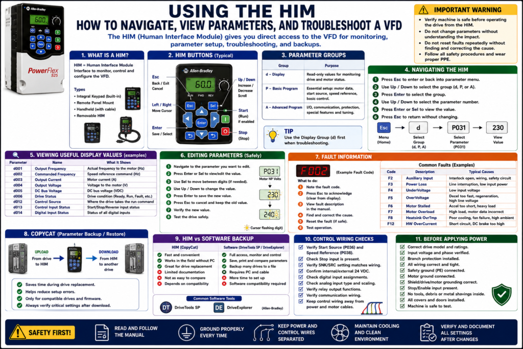
The HIM, or Human Interface Module, is one of the most useful tools a technician can use when working with a Variable Frequency Drive.
A VFD can be controlled and diagnosed from different places: PLC, HMI, terminal block, communication network, software, or keypad. The HIM gives the technician direct access to the drive so they can view status, monitor output values, check fault codes, adjust speed locally, change parameters, and, on supported models, copy or transfer parameter sets.
A HIM is especially useful during:
Startup
Troubleshooting
Drive replacement
Parameter verification
Local testing
Fault review
Speed adjustment
Backup and restore
Maintenance work
The examples in this post use Allen-Bradley PowerFlex drives as a practical reference, but the same concept applies to most VFD brands. Some manufacturers call it a keypad, operator panel, control panel, display module, or drive operator interface.
1. What Is a HIM?
HIM stands for:
Human Interface ModuleIt is the operator/technician interface for the VFD.
Depending on the drive model, the HIM may be:
Built into the drive
Mounted remotely on the panel door
Handheld and connected with a cable
Removable from the drive
Used only for programming and troubleshooting
On Allen-Bradley PowerFlex drives, HIM options may include a fixed keypad, remote panel-mount display, or handheld module. PowerFlex documentation lists remote HIM options with LCD display, digital speed control, full numeric keypad on handheld versions, and CopyCat capability on supported modules.
2. Why the HIM Matters for Technicians
The HIM allows the technician to interact directly with the VFD without needing the PLC or HMI.
With a HIM, a technician may be able to:
View output frequency
View commanded frequency
View output current
View DC bus voltage
View drive status
View control source
View digital input status
View fault history
Acknowledge or clear faults
Edit parameters
Start/stop the drive locally, if enabled
Change speed locally, if enabled
Copy parameters, if supported
Most VFDs, and specifically PowerFlex 4, the condition or state of the drive is constantly monitored and changes are indicated on the integral keypad. It also notes that when a fault occurs, the keypad provides visual notification with a flashing fault code and flashing fault indicator.
3. HIM vs HMI
A common source of confusion is HIM vs HMI.
They sound similar, but they are not the same.
| Term | Meaning | Typical Location | Purpose |
|---|---|---|---|
| HIM | Human Interface Module | On or near the VFD | Direct drive programming and monitoring |
| HMI | Human-Machine Interface | Operator panel or SCADA screen | Machine/process operation |
Simple explanation:
HIM = talks directly to the drive.
HMI = talks to the machine control system.
The HMI may show the operator a clean screen like:
Motor Running
VFD Faulted
Speed Setpoint
Output Frequency
Reset Fault
The HIM shows the technician direct drive information such as:
d001 Output Frequency
d003 Output Current
P036 Start Source
P038 Speed Reference
Fault Code
4. Local Control vs Remote Control
One of the most important things to understand when using a HIM is whether the drive is in local or remote control.
Local control usually means the drive is being controlled from the keypad/HIM.
Remote control usually means the drive is being controlled from:
Terminal block
PLC outputs
Analog input
Communication network
External controller
Local control means operation is done through the keypad on the front of the drive or a local control panel, where the operator or technician monitors and controls the drive through that keypad.
Technician Warning
Before pressing Start from the HIM, always verify:
[ ] Is it safe for the motor to run?
[ ] Is the machine clear?
[ ] Is the drive in Local or Remote?
[ ] Is the speed reference safe?
[ ] Is the direction correct?
[ ] Are safety interlocks active?
[ ] Is the process ready?
A HIM is powerful because it can sometimes bypass the normal operator interface. Use it carefully.
5. Common HIM Buttons
Every drive brand is different, but many HIM/keypad layouts include similar buttons.
Common buttons:
| Button | Typical Function |
|---|---|
| ESC | Back out of menu / acknowledge fault display |
| SEL | Select digit or parameter field |
| ENTER | Accept selection or save value |
| UP | Increase value or scroll up |
| DOWN | Decrease value or scroll down |
| START | Start drive, if enabled |
| STOP | Stop drive |
| REV | Reverse direction, if enabled |
| RESET | Reset fault, if supported |
Esc, Up/Down, Enter, and Sel to navigate parameter groups, view values, edit digits, cancel changes, or save changes.
6. Understanding Parameter Groups
VFD parameters are usually organized into groups.
For PowerFlex-style drives, common groups include:
d = Display Group
P = Basic Program Group
A = Advanced Program Group
The PowerFlex manual explains that parameter numbers and names are shown with a group letter, number, and parameter name, such as P031 [Motor NP Volts]. It also identifies groups such as Display, Basic Program, and Advanced Program.
Typical Parameter Group Purpose
| Group | Purpose |
|---|---|
| Display Group | Read-only monitoring values |
| Basic Program Group | Basic motor and control setup |
| Advanced Program Group | I/O, communication, protection, advanced features |
A technician should use the Display Group first when troubleshooting because it shows what the drive is actually seeing.
7. Viewing Parameters from the HIM
The exact steps depend on the drive model, but a basic flow looks like this:
1. Press ESC to enter or back into the parameter menu.
2. Use UP/DOWN to select the parameter group.
3. Press ENTER to select the group.
4. Use UP/DOWN to select the parameter number.
5. Press ENTER or SEL to view the value.
6. Press ESC to return without changing.
After power-up the drive displays a Display Group parameter, pressing Esc shows the parameter number, pressing Esc again allows group selection, Up/Down scrolls through groups, and Enter selects the group.
Good First Parameters to View
When troubleshooting, useful display values include:
Output Frequency
Commanded Frequency
Output Current
Output Voltage
DC Bus Voltage
Drive Status
Control Source
Digital Input Status
Fault Code
On a PowerFlex-style drive, examples may include:
d001 Output Frequency
d002 Commanded Frequency
d003 Output Current
d004 Output Voltage
d005 DC Bus Voltage
d006 Drive Status
d012 Control Source
d013 Control Input Status
d014 Digital Input Status
These values help you avoid guessing.
8. Editing Parameters from the HIM
Before editing any parameter, follow this rule:
Record the original value first.Basic editing flow:
1. Navigate to the parameter.
2. Press ENTER or SEL to view/edit the value.
3. Use SEL to move between digits, if needed.
4. Use UP/DOWN to change the value.
5. Press ENTER to save.
6. Press ESC to cancel or back out.
7. Verify the new value.
8. Test operation safely.
Pressing Enter or Sel allows viewing or editing a parameter value, Sel can move digit to digit, Esc cancels a change and restores the previous value, and Enter saves the change.
Technician Note
Never change parameters randomly.
Before changing any value, ask:
[ ] What does this parameter control?
[ ] What is the current value?
[ ] What should the correct value be?
[ ] Is there a backup?
[ ] Is the machine safe to test after the change?
[ ] Does the change affect safety, speed, direction, braking, or restart behavior?
9. Viewing Faults from the HIM
When a VFD faults, the HIM/keypad usually displays a fault code or fault message.
A PowerFlex troubleshooting section explains that the integral keypad provides visual notification of a fault by displaying a flashing fault number and flashing fault indicator, and the technician can press Esc to regain control of the keypad.
Common fault information may include:
Fault code
Fault description
Fault history
Time of fault, if supported
Drive status at fault
Output current at fault, if supported
DC bus voltage at fault, if supported
Do Not Reset Blindly
A fault is information.
Before resetting, record:
[ ] Fault code
[ ] Fault description
[ ] Operating condition
[ ] Motor speed
[ ] Load condition
[ ] Whether it happened during start, run, or stop
[ ] Any recent parameter or wiring changes
Then troubleshoot the cause.
10. Common Faults You May See on a HIM
Common VFD faults include:
| Fault Type | What to Think About |
|---|---|
| Overcurrent | Load, motor wiring, accel time, short circuit |
| Overvoltage | Decel too fast, regeneration, high line voltage |
| Undervoltage | Low input voltage, phase loss, power interruption |
| Motor Overload | Motor FLA setting, load, cooling, duty |
| Ground Fault | Motor cable, motor winding, moisture |
| Overtemperature | Fan, heatsink, cabinet cooling |
| Communication Loss | Network cable, adapter, node/IP settings |
| Analog Input Loss | Speed signal, sensor, wiring, scaling |
The PowerFlex troubleshooting material includes fault descriptions and corrective actions for faults such as Power Loss, UnderVoltage, OverVoltage, Motor Stalled, Motor Overload, Heatsink Overtemperature, Hardware OverCurrent, and Ground Fault.
11. Using HIM Display Values for Troubleshooting
The HIM is extremely useful because it can show what the drive is seeing in real time.
Example 1: PLC Says Run, But Drive Does Not Run
Check:
Control Source
Digital Input Status
Drive Status
Fault Code
Commanded Frequency
Possible findings:
Start Source is set to Keypad.
Terminal input is not active.
Stop input is missing.
Drive is faulted.
Speed reference is 0 Hz.
Example 2: Motor Runs at Wrong Speed
Check:
Commanded Frequency
Output Frequency
Speed Reference Source
Analog Input Value
Preset Speed Inputs
Control Source
Possible findings:
Drive is in Local mode.
Speed reference is Keypad.
Analog input is missing.
Preset speed is active.
Network reference is not being received.
Example 3: Drive Trips During Stop
Check:
Fault Code
DC Bus Voltage
Stop Mode
Decel Time
Dynamic Brake Settings
Output Frequency
Possible finding:
OverVoltage during deceleration because the load is regenerating energy back into the DC bus.12. HIM CopyCat Function
Some HIM modules support a parameter copy function often called CopyCat.
CopyCat can allow the technician to:
Upload parameters from a drive to the HIM
Store the parameter set
Download parameters from the HIM to another compatible drive
Speed up replacement work
Reduce manual parameter entry errors
PowerFlex documentation lists both remote panel-mount and handheld HIM options as CopyCat capable. The handheld version also includes a full numeric keypad and cable, while the remote panel-mount version includes an LCD display and digital speed control.
CopyCat Use Case
A common field scenario:
Old VFD is still powering up.
Technician uploads parameter set into HIM.
Old drive is replaced.
Technician downloads parameter set into replacement drive.
Technician verifies motor data, I/O, communication, and direction.
This can save a lot of time.
CopyCat Warning
CopyCat is not magic.
Always verify:
[ ] Drive family compatibility
[ ] Firmware compatibility
[ ] Horsepower/current rating compatibility
[ ] Input voltage rating
[ ] Parameter structure
[ ] Communication settings
[ ] Motor nameplate data
[ ] Start source and speed reference
[ ] Digital input functions
[ ] Relay output functions
[ ] Direction of rotation
A copied configuration should always be verified before returning the machine to production.
13. HIM vs Software Backup
A HIM is great in the field, but software may provide better documentation.
Examples of software tools:
DriveTools SP
DriveExplorer
DriveExecutive
Connected Components Workbench
Manufacturer-specific software
PowerFlex documentation describes DriveTools SP as Windows-based software that provides a way to monitor or configure Allen-Bradley drives and communication adapters online and offline. It also describes DriveExplorer as software used to monitor or configure drives and adapters online/offline.
Comparison
| Method | Best For | Limitation |
|---|---|---|
| HIM | Fast local access in the field | Small display, limited documentation |
| HIM CopyCat | Quick replacement between compatible drives | Compatibility must be verified |
| DriveTools SP / DriveExplorer | Backup, compare, print, online/offline work | Requires PC, cable, software compatibility |
| Manual Parameter Sheet | Universal method | Time-consuming, prone to errors |
| PLC-based parameters | Some networked systems | Not always complete |
14. Using the HIM During Drive Replacement
Before removing the old drive:
[ ] View and record fault history.
[ ] Record motor nameplate parameters.
[ ] Record Start Source.
[ ] Record Speed Reference.
[ ] Record Accel/Decel Times.
[ ] Record Stop Mode.
[ ] Record digital input functions.
[ ] Record relay output functions.
[ ] Record analog input settings.
[ ] Record communication settings.
[ ] Upload parameters using HIM CopyCat if supported.
[ ] Save software backup if possible.
After installing the replacement drive:
[ ] Download or enter parameters.
[ ] Verify motor data.
[ ] Verify start source.
[ ] Verify speed reference.
[ ] Verify I/O status.
[ ] Verify communication.
[ ] Test local mode safely.
[ ] Test remote/auto mode safely.
[ ] Verify motor rotation.
[ ] Verify feedback to PLC/HMI.
[ ] Save final backup.
15. Safety When Using the HIM
Using a HIM may seem simple, but the drive may be energized and capable of starting a motor.
Before using the HIM:
[ ] Know whether the drive is energized.
[ ] Follow required PPE rules.
[ ] Keep hands away from live terminals.
[ ] Understand local/remote mode.
[ ] Confirm the motor can safely run.
[ ] Do not change parameters without authorization.
[ ] Do not reset faults repeatedly without finding the cause.
[ ] Do not use local start if the machine is not clear.
The PowerFlex manual warns that only qualified personnel familiar with AC drives and associated machinery should plan, install, start up, or maintain the system. It also warns that the drive contains high-voltage capacitors that require time to discharge after power is removed.
16. Common HIM Mistakes
Avoid these mistakes:
[ ] Pressing Start locally without confirming machine status
[ ] Changing parameters without recording original values
[ ] Confusing output frequency with commanded frequency
[ ] Resetting faults without documenting the fault code
[ ] Leaving the drive in Local mode after troubleshooting
[ ] Assuming HIM speed is the same as PLC speed reference
[ ] Copying parameters to an incompatible replacement drive
[ ] Forgetting communication settings after replacement
[ ] Not verifying digital input status from the HIM
[ ] Not saving a final backup after changes
17. Practical Troubleshooting Flow Using the HIM
When the drive is not running:
1. Check fault code.
2. Check drive status.
3. Check control source.
4. Check digital input status.
5. Check commanded frequency.
6. Check output frequency.
7. Check output current.
8. Check speed reference source.
9. Check stop/enable input.
10. Verify local/remote mode.
When the drive is running but not correctly:
1. Check commanded frequency vs output frequency.
2. Check current.
3. Check DC bus voltage.
4. Check acceleration/deceleration settings.
5. Check speed reference source.
6. Check active preset speeds.
7. Check analog input signal.
8. Check fault/alarm history.
Simple Technician Explanation
A simple way to explain the HIM is:
The HIM is the technician’s direct window into the VFD.
It lets you see what the drive is doing, what it is commanded to do, and what fault or parameter may be stopping it from running correctly.
Or even shorter:
HIM = direct access to drive status, parameters, faults, and sometimes backups.Final Thoughts
The HIM is one of the most practical tools for VFD troubleshooting.
A good technician uses the HIM to avoid guessing. Instead of only looking at the PLC or HMI, the technician checks what the drive itself is seeing:
Is the drive faulted?
What is the active control source?
Is the start input active?
Is the speed reference present?
What is the output frequency?
What is the output current?
What fault code occurred?
Are the parameters correct?
For VFD replacement, the HIM can also help with parameter transfer when CopyCat is supported. But even when using CopyCat, the technician must verify compatibility, motor data, I/O, communication, direction, and final operation.
A strong VFD troubleshooting mindset is:
Use the HIM to verify.
Use backups to protect the process.
Use the manual to confirm.
Use safe testing before returning to production.