9. VFD Installation Basics: Power Wiring, Control Wiring, Grounding, and Environment (9 of 19)
Introduction
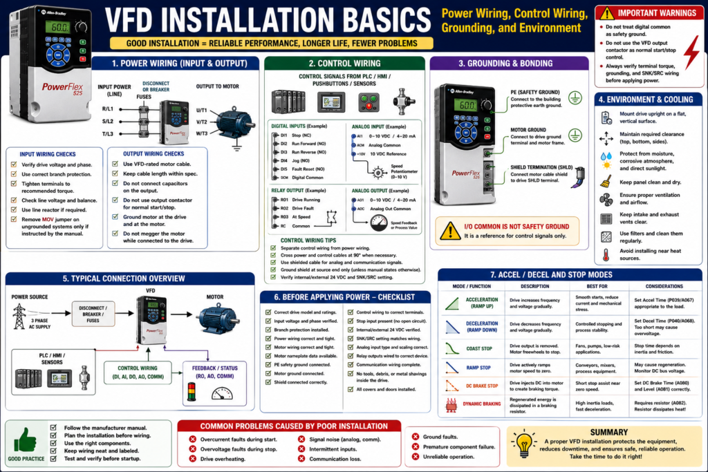
A Variable Frequency Drive can be correctly programmed and still fail if it is installed incorrectly.
Many VFD problems in the field are not caused by a bad drive. They are caused by installation issues such as poor grounding, wrong wire routing, loose terminals, incorrect branch protection, improper control wiring, blocked airflow, excessive heat, moisture, dust, or incorrect output wiring to the motor.
A good VFD installation must consider:
Power wiring
Control wiring
Grounding and bonding
Motor cable routing
Shielding
Branch circuit protection
Input power quality
Panel environment
Cooling and airflow
Manufacturer instructions
The examples in this post use Allen-Bradley PowerFlex drives as a practical reference, but the installation concepts apply to most industrial VFDs regardless of manufacturer.
The PowerFlex 4 manual states that most start-up difficulties are the result of incorrect wiring, and that all wiring instructions should be read and understood before installation begins.
1. Always Start with the Manufacturer Manual
Before installing or replacing a VFD, always verify the manufacturer manual for the exact model.
A VFD installation is not a “one-size-fits-all” job.
Different drives may have different requirements for:
Input voltage
Output current
Branch protection
Grounding
MOV removal
Terminal torque
Motor cable length
Control input wiring
SNK/SRC configuration
EMC filtering
Clearance
Cooling
Enclosure rating
Technician should check the user manual before wiring practical VFD circuits.
2. Mounting the Drive Correctly
A VFD must be physically mounted in a way that supports cooling, serviceability, and reliability.
Typical installation requirements include:
Mount upright
Use a flat, vertical, level surface
Maintain required clearances
Protect from dust and metal particles
Protect from moisture
Protect from corrosive atmospheres
Avoid direct sunlight
Allow airflow around heatsinks and fans
The PowerFlex 4 manual states that the drive should be mounted upright on a flat, vertical, level surface, and that the cooling fan should be protected by avoiding dust or metallic particles. It also warns not to expose the drive to a corrosive atmosphere, moisture, or direct sunlight.
Technician Note
Before mounting a VFD, ask:
[ ] Is there enough clearance around the drive?
[ ] Is the panel temperature controlled?
[ ] Is there proper ventilation?
[ ] Are cabinet fans and filters in good condition?
[ ] Can dust or metal shavings enter the drive?
[ ] Is the environment wet, corrosive, or high temperature?
[ ] Is the enclosure rating correct for the location?
3. Environmental Conditions Matter
VFDs are electronic power devices. Their environment directly affects life and reliability.
Common environmental problems include:
Excessive heat
Dust buildup
Conductive dust
Metal shavings
Moisture
Condensation
Washdown exposure
Corrosive chemicals
Poor ventilation
Blocked heatsinks
Failed cooling fans
Dirty filters
Moisture, sunlight, and corrosive atmospheres can harm VFDs, and that manufacturers provide specifications for mounting and installing the drive.
Common Field Example
Problem:
Drive faults on overtemperature during production.Possible installation-related causes:
[ ] Cabinet fan failed
[ ] Cabinet filter clogged
[ ] Drive heatsink dirty
[ ] Drive mounted too close to other heat-producing equipment
[ ] Panel located in hot environment
[ ] Airflow blocked
[ ] Wrong enclosure for the application
4. Input Power Wiring
Input power wiring is the line-side wiring feeding the VFD.
Typical VFD input terminals may be labeled:
R/L1
S/L2
T/L3
Depending on the drive, input power may be:
Single-phase
Three-phase
120 VAC
240 VAC
480 VAC
575 VAC
Always verify the drive nameplate and manual before applying power.
The PowerFlex 400 terminal information identifies R/L1, S/L2, T/L3 as 3-phase input terminals and U/T1, V/T2, W/T3 as motor output terminals.
Input Power Checks
Before applying power:
[ ] Confirm input voltage matches drive rating.
[ ] Confirm phase count matches drive rating.
[ ] Check disconnect, fuses, or breaker.
[ ] Verify proper wire size.
[ ] Verify terminal torque.
[ ] Check phase balance.
[ ] Check for loose terminals.
[ ] Check grounding.
[ ] Verify line reactor or isolation transformer if required.
The PowerFlex 400 documentation notes that terminal screws may become loose during shipment and should be tightened to the recommended torque before applying power.
5. Branch Circuit Protection
A VFD still needs proper upstream branch circuit protection.
Do not assume the VFD replaces fuses or circuit breakers.
The PowerFlex 4 manual states that the drive does not provide branch short-circuit protection and should be installed with input fuses or an input circuit breaker. It also notes that national and local industrial safety regulations or electrical codes may determine additional requirements.
Technician Note
Verify:
[ ] Correct fuse type
[ ] Correct fuse size
[ ] Correct breaker type
[ ] Correct SCCR requirements
[ ] Correct conductor size
[ ] Correct disconnect rating
[ ] Local and national code requirements
[ ] Manufacturer recommendations
Incorrect protection can create serious safety and equipment damage risks.
6. Input Power Quality and Line Reactors
Some input power conditions can damage the drive or reduce its life.
Examples include:
Low line impedance
Large supply transformer
Power factor correction capacitors on the line
Frequent power interruptions
High noise spikes
Lightning-related transients
Ungrounded distribution systems
High phase-to-ground voltage
The PowerFlex 4 manual lists input power conditions that may cause component damage or reduced product life, and recommends corrective actions such as installing a line reactor, isolation transformer, or removing the MOV jumper to ground in certain systems.
When a Line Reactor May Be Needed
A line reactor may help when:
[ ] The drive is close to a large transformer.
[ ] The input power has frequent spikes.
[ ] There are power factor correction capacitors nearby.
[ ] The facility has unstable incoming power.
[ ] Multiple drives are on the same distribution.
[ ] The drive experiences nuisance input-related faults.
A glossary definition describes a reactor as an electrical circuit made up of inductors and/or capacitors, often used to filter electrical noise from a circuit.
7. Ungrounded Systems and MOVs
Some VFDs contain MOVs connected to ground for surge protection. In certain ungrounded or high phase-to-ground voltage systems, these may need to be disconnected according to the manufacturer manual.
Failing to disconnect MOVs on ungrounded AC systems can result in severe drive damage and that the user should always check the drive manual for specific instructions.
The PowerFlex 4 manual also states that on ungrounded distribution systems where line-to-ground voltage can exceed 125% of nominal line-to-line voltage, the MOVs connected to ground should be disconnected to prevent drive damage.
Technician Warning
Do not remove MOV jumpers blindly.
Only do this when:
[ ] The system type requires it.
[ ] The manufacturer manual instructs it.
[ ] The work is performed by qualified personnel.
[ ] The change is documented.
8. Output Power Wiring to the Motor
The VFD output terminals feed the motor.
Typical output terminals:
U/T1
V/T2
W/T3
The output of a VFD is not the same as normal utility power. It is an electronically generated PWM output.
Important output wiring considerations:
Use proper motor cable
Follow cable length recommendations
Ground the motor properly
Avoid unnecessary output contactors
Do not connect capacitors to the VFD output
Do not megger the motor while connected to the drive
Route motor cables away from control wiring
Use output reactors or filters when required
The PowerFlex troubleshooting information lists ground faults and phase-to-phase shorts as output-related faults, with corrective actions such as checking the wiring between the drive and motor and checking the motor for grounded phases or shorted conditions.
9. Do Not Use Output Contactors as Normal Start/Stop Control
VFDs are intended to be controlled by command inputs, not by repeatedly opening and closing the motor output circuit while the drive is running.
VFDs are intended to be commanded by control input signals. It warns that a device that disconnects and reapplies output power to the motor should not be used as normal control; if required for situations such as Emergency Stop, auxiliary contacts should be used to simultaneously disable the drive run command.
Bad Normal Control Practice
VFD output active → Output contactor opens → Motor disconnected under loadBetter Normal Control Practice
Remove Run Command → Drive stops output → Motor stops according to Stop ModeEmergency stop and safety circuits must be designed according to the machine risk assessment and applicable safety standards.
10. Control Wiring Basics
Control wiring includes low-voltage signals used to command and monitor the VFD.
Common control wiring includes:
Digital inputs
Analog inputs
Relay outputs
Digital outputs
Analog outputs
Communication cables
HIM/keypad cables
Fault reset wiring
Enable/interlock wiring
Remote control signals are typically wired into the terminal strip and include four types: digital inputs, analog inputs, digital/relay outputs, and analog outputs. Digital inputs are on/off signals such as start, stop, reverse, jog, or speed change; analog inputs are proportional signals used for speed reference or feedback.
Control Wiring Checklist
[ ] Verify terminal numbers.
[ ] Verify digital common.
[ ] Verify internal vs external 24 VDC.
[ ] Verify SNK/SRC setup.
[ ] Verify analog signal type.
[ ] Verify shield termination.
[ ] Verify stop input.
[ ] Verify enable input.
[ ] Verify fault reset input.
[ ] Verify relay output function.
[ ] Verify communication wiring.
11. Digital Input Wiring: SNK/SRC
Many VFDs support sink/source digital input wiring.
This must match the control wiring scheme.
The VFD start-up material says the technician should verify that the SNK/SRC setup DIP switch is set to match the control wiring scheme before operation.
If SNK/SRC is wrong, the drive may not see the inputs correctly.
Symptoms:
[ ] Start input does not work.
[ ] Stop input does not work.
[ ] PLC output is ON but VFD input status is OFF.
[ ] Inputs appear inverted or dead.
[ ] Drive only works with jumpers.
12. Stop Input and Enable Wiring
Many drives require a stop or enable input to be present before they will run.
The VFD start-up material states that the PowerFlex 4 will not start unless a stop input is present.
This is a very common troubleshooting point.
If a drive powers up but does not start from terminal block inputs, check:
[ ] Is the stop input present?
[ ] Is the factory jumper required?
[ ] Was the jumper removed correctly?
[ ] Is an external safety/interlock circuit open?
[ ] Is the drive configured for the correct start source?
[ ] Is the input status changing on the display?
13. Analog Input Wiring
Analog inputs are commonly used for speed reference or process feedback.
Common analog signals:
0–10 VDC
4–20 mA
0–20 mA
Potentiometer input
Important checks:
[ ] Is the drive configured for voltage or current?
[ ] Is the DIP switch set correctly?
[ ] Is the analog common correct?
[ ] Is polarity correct?
[ ] Is the signal scaled correctly?
[ ] Is shielded cable used?
[ ] Is the shield terminated correctly?
[ ] Is noise affecting the signal?
Analog problems often look like drive problems, but the actual issue may be signal type, scaling, common wiring, or electrical noise.
14. Relay Output and Feedback Wiring
VFD relay outputs are often used to send status back to a PLC or HMI.
Common relay output functions:
Drive Running
Drive Faulted
Drive Ready
At Speed
Motor Running
Alarm
Digital/relay outputs are on/off signals sent from the VFD to devices such as indicator lights, alarms, or signals showing that the load reached a specified speed. It also notes that relay outputs are dry contacts.
Technician Note
A relay output is only useful if the relay function parameter is correct.
Example:
The PLC input is labeled VFD_Running,
but the VFD relay is configured as Drive Ready.
That creates bad feedback and operator confusion.
15. Grounding: PE, Motor Ground, and Shields
Grounding is one of the most important parts of VFD installation.
The drive safety ground must be connected to the system ground, and ground impedance must meet national/local regulations and electrical codes. The PowerFlex manual also states that the integrity of ground connections should be periodically checked.
The PowerFlex manual identifies:
Safety Ground - PE
Motor Ground
Shield Termination - SHLD
RFI Filter Grounding
It states that the motor ground must be connected to one of the drive ground terminals, and that the motor cable shield should be connected to a safety ground terminal at the drive end and to the motor frame at the motor end.
Safety Ground Is Not Digital Common
This is critical:
Safety Ground ≠ Digital CommonI/O terminals labeled “Common” are not referenced to ground; they are shared source terminals, not safety grounds.
This matters when troubleshooting 24 VDC input circuits, analog signals, and control wiring.
16. Shielding and Noise Control
VFDs can generate electrical noise because of high-speed switching.
Noise can affect:
Analog signals
Communication cables
PLC inputs
Encoder signals
HMI communication
Instrumentation
Nearby control circuits
Shielded cable is used for control and signal wiring, the shield should be grounded at the source end only, not at the drive end.
Good Wiring Practices
[ ] Separate power and control wiring.
[ ] Cross power and control wires at 90 degrees when needed.
[ ] Use shielded cable for analog signals.
[ ] Use proper motor cable when required.
[ ] Terminate shields according to the manual.
[ ] Keep communication cables away from motor leads.
[ ] Bond the panel and drive properly.
[ ] Avoid ground loops in signal wiring.
17. Communication Wiring
Modern VFDs may communicate with PLCs and HMIs through:
EtherNet/IP
Modbus RTU
Modbus TCP
PROFIBUS
PROFINET
DeviceNet
RS485 / DSI
CANopen
Vendor-specific networks
Installation issues can cause communication faults.
Check:
[ ] Correct cable type.
[ ] Correct connector.
[ ] Correct shielding.
[ ] Correct termination resistor, if required.
[ ] Correct node address or IP address.
[ ] Correct baud/data rate.
[ ] Cable routed away from motor leads.
[ ] Network ground/shield practice follows manual.
The PowerFlex troubleshooting table lists communication loss as a fault condition and recommends checking the port wiring, connection, adapter, or drive when communication stops unexpectedly.
18. Before Applying Power
Before power-up, verify:
[ ] Correct drive model.
[ ] Correct input voltage.
[ ] Correct branch protection.
[ ] Correct input wiring.
[ ] Correct motor wiring.
[ ] Correct ground wiring.
[ ] Correct terminal torque.
[ ] Motor leads are not shorted or grounded.
[ ] Control inputs are on correct terminals.
[ ] SNK/SRC setting matches wiring.
[ ] Analog signal type is correct.
[ ] Stop input is present.
[ ] Output contactor is not being used incorrectly.
[ ] Panel is clean.
[ ] Fans and ventilation are OK.
The VFD start-up material states that before applying power, the technician should verify all inputs are connected to the correct terminals and secure, and that some voltages during start-up can be lethal.
19. Common Installation Mistakes
[ ] Mounting the drive with poor airflow
[ ] Leaving metal shavings inside the panel
[ ] Installing the drive in a wet or corrosive location
[ ] Incorrect fuse or breaker selection
[ ] Wrong input voltage
[ ] Loose power terminals
[ ] Missing motor ground
[ ] Treating digital common as safety ground
[ ] Routing analog signal cable with motor leads
[ ] Wrong SNK/SRC setting
[ ] Missing stop input
[ ] Wrong analog input DIP switch
[ ] Using output contactor as normal start/stop
[ ] Not checking MOV requirements on ungrounded systems
[ ] Not documenting wiring and parameter changes
20. Technician Checklist: VFD Installation Basics
[ ] Read the specific drive manual.
[ ] Verify drive voltage and current rating.
[ ] Confirm correct branch circuit protection.
[ ] Verify input power wiring.
[ ] Verify output motor wiring.
[ ] Confirm motor nameplate data.
[ ] Confirm motor ground.
[ ] Confirm PE safety ground.
[ ] Verify shield termination.
[ ] Separate power and control wiring.
[ ] Verify control terminals.
[ ] Verify internal/external 24 VDC wiring.
[ ] Verify SNK/SRC setting.
[ ] Verify analog input type and scaling.
[ ] Verify relay output wiring.
[ ] Verify communication wiring.
[ ] Check stop/enable input.
[ ] Check airflow and cooling.
[ ] Check cabinet environment.
[ ] Tighten terminals to specified torque.
[ ] Document wiring and parameters.
Simple Technician Explanation
A simple way to explain VFD installation is:
A VFD installation must protect the drive, protect the motor, reduce electrical noise, maintain proper cooling, and make sure the control signals match the parameter setup.Or even shorter:
Good wiring + good grounding + good cooling = reliable VFD operation.Final Thoughts
VFD installation is not only about landing wires on terminals. It is about creating a reliable power, control, grounding, and environmental system around the drive.
A good technician does not only ask:
Is the drive programmed correctly?A good technician also asks:
Is the drive installed correctly?
Is the power clean?
Is the grounding correct?
Is the motor cable correct?
Is the control wiring separated?
Is the cabinet environment suitable?
Is the stop input present?
Is the SNK/SRC setup correct?
Many VFD issues can be prevented before startup by following the manual, checking the wiring, verifying grounding, and documenting the installation.
Correct installation prevents future troubleshooting.