7. 2-Wire vs 3-Wire VFD Control (7 of 19)
Introduction
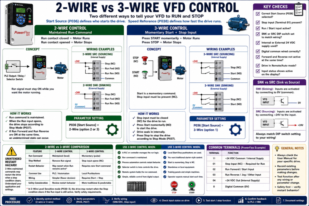
When a Variable Frequency Drive is controlled from external pushbuttons, selector switches, relays, or PLC outputs, the technician must understand the difference between 2-wire control and 3-wire control.
These two control methods define how the VFD receives its Run and Stop commands.
A VFD may be perfectly healthy, the motor may be good, and the power wiring may be correct, but the motor still may not start if the drive is configured for the wrong control method.
In simple terms:
2-Wire Control = maintained Run command
3-Wire Control = momentary Start command with Stop input
The examples in this post use Allen-Bradley PowerFlex drives as a practical reference, but the concepts apply to most industrial VFDs regardless of manufacturer.
Why This Topic Matters
Understanding 2-wire and 3-wire control helps technicians troubleshoot problems like:
[ ] Drive does not start from terminal block
[ ] Drive only starts from keypad/HIM
[ ] Drive restarts unexpectedly
[ ] Stop input is missing
[ ] PLC output is ON but motor does not run
[ ] Start pushbutton works differently than expected
[ ] Drive starts but direction control is wrong
[ ] Sink/source wiring does not match the drive setup
The PowerFlex manual troubleshooting table specifically says that if a drive does not start from Start or Run inputs, the technician should verify that the Start signal is present, verify Terminal 01 is active, verify that the Start Source matches the configuration, and confirm correct input wiring. It also notes that 2-wire control requires Run Forward, Run Reverse, or Jog input, while 3-wire control requires Start and Stop inputs.
1. What Is 2-Wire VFD Control?
2-wire control uses a maintained signal to command the drive to run.
A simple way to understand it:
Run contact closed = Drive runs
Run contact open   = Drive stops
This is common when the VFD is controlled by:
Maintained selector switch
PLC digital output
Relay contact
Run permissive circuit
HOA Auto command
Remote control system
A typical 2-wire command is not a quick pulse. It must stay active while the motor is expected to run.
Basic 2-Wire Example
PLC Output ON  → VFD Run Input ON  → Motor Runs
PLC Output OFF → VFD Run Input OFF → Motor Stops
For a PowerFlex-style example:
P036 [Start Source] = 2-WireThe PowerFlex manual describes 2-wire SRC and SNK control using Run Forward / Run Reverse inputs. It notes that the input must be active for the drive to run, and when the input opens, the drive stops according to the configured Stop Mode.
Where 2-Wire Control Is Common
2-wire control is very common in automated systems because the PLC usually maintains the Run command.
Examples:
PLC-controlled conveyor
Pump controlled by pressure switch or PLC output
Fan controlled by BAS or PLC
Mixer enabled by sequence logic
Remote run command from a relay
HOA selector in Auto mode
In a PLC system, the PLC logic normally decides whether the Run command should remain ON.
2. What Is 3-Wire VFD Control?
3-wire control is more like a traditional motor starter pushbutton circuit.
It normally uses:
Stop input
Start input
Common/control power reference
The Start command is usually momentary, not maintained.
A simple way to understand it:
Press Start momentarily → Drive starts
Press Stop              → Drive stops
For a PowerFlex-style example:
P036 [Start Source] = 3-WireThe PowerFlex manual describes 3-wire control as using a momentary input to start the drive, while a Stop input to Terminal 01 stops the drive according to the Stop Mode.
Basic 3-Wire Example
Stop PB = normally closed input
Start PB = normally open momentary input

Press Start → VFD starts
Release Start → VFD continues running internally
Press Stop → VFD stops
The drive handles the internal “seal-in” behavior.
Where 3-Wire Control Is Common
3-wire control is common when operators use physical pushbuttons.
Examples:
Local Start/Stop station
Standalone VFD panel
Machine-mounted pushbutton station
Manual process equipment
Training panels
Small systems without PLC control
It feels familiar to technicians who have worked with motor starter circuits.
3. Main Difference Between 2-Wire and 3-Wire Control
| Feature | 2-Wire Control | 3-Wire Control |
|---|---|---|
| Run command type | Maintained | Momentary Start |
| Stop method | Remove Run command or Stop input | Stop input opens |
| Typical device | Selector switch, relay, PLC output | Start/Stop pushbuttons |
| Restart behavior | Can restart if Run remains active, depending on mode | Usually requires a new Start command |
| Common use | PLC/remote automation | Local pushbutton control |
| Troubleshooting focus | Is Run input active? | Are Start and Stop inputs correct? |
Simple Technician Explanation
2-Wire = “Keep this signal ON while I want the motor running.”
3-Wire = “Press Start once, press Stop to stop.”
That simple distinction solves a lot of confusion in the field.
4. The Stop Input Is Critical
Many VFDs require a Stop or Enable input to be present before the drive will start.
On PowerFlex 4 drives, Terminal 01 is used as a Stop input by default. The manual states that a factory-installed jumper or normally closed input must be present for the drive to start. It also explains that the jumper between Terminals 01 and 11 should be removed when Terminal 01 is used as a Stop or Enable input.
This is a very common field issue:
Drive powers up.
Keypad works.
Start command is present.
But the drive will not run.
Possible cause:
Stop input is missing.Technician Note
Before blaming the drive, check:
[ ] Is the Stop input present?
[ ] Is the factory jumper installed when required?
[ ] Was the jumper removed when using a real Stop input?
[ ] Is the Stop contact normally closed?
[ ] Is the safety/interlock circuit open?
[ ] Is the drive configured for 2-wire or 3-wire correctly?
Start-up check, stating that the drive will not start unless a Stop input is present.
5. 2-Wire Control and Restart Behavior
2-wire control is powerful, but technicians must respect the restart behavior.
Because the Run command is maintained, the drive may restart when a Stop condition clears, depending on the configuration.
The PowerFlex manual warns that with a 2-wire level-sensitive start source, if the Run input is maintained, the Run input does not need to be toggled after a Stop input for the drive to run again. The manual identifies this as an unintended-operation hazard.
This matters in real automation.
Example:
Run command remains ON.
Stop input opens due to interlock.
Motor stops.
Interlock clears.
Drive may restart automatically.
That may be acceptable in some automated systems, but it may be unsafe or unexpected in others.
Technician Warning
Always verify:
[ ] Does the drive require a new rising edge to restart?
[ ] Does it restart when Stop is removed?
[ ] Is Auto Restart enabled?
[ ] Is the PLC still holding Run command ON?
[ ] Is the operator expecting manual restart?
[ ] Is this behavior safe for the machine?
6. 2-Wire Forward / Reverse Control
Many VFDs allow 2-wire commands for both forward and reverse.
Example:
Run Forward input active = Motor runs forward
Run Reverse input active = Motor runs reverse
Important warning:
Run Forward and Run Reverse should not be commanded at the same time.The PowerFlex manual notes that if both Run Forward and Run Reverse inputs are closed at the same time, an undetermined state could occur.
PLC Logic Recommendation
In PLC control, avoid energizing both directions together.
Use interlock logic:
VFD_RunFwd_Cmd = Forward_Request AND NOT Reverse_Request
VFD_RunRev_Cmd = Reverse_Request AND NOT Forward_Request
Better yet, use a central command structure:
Request → Permissives → Direction Selection → VFD Command7. 3-Wire Control with Direction Selection
In 3-wire control, the Start input may be momentary, while direction can be selected separately.
Example:
Stop input = NC maintained
Start input = NO momentary
Direction selector = Forward / Reverse
A practical exercises where the student draws wiring diagrams for 3-wire SNK control with a reversing switch and 3-wire SRC control with a reversing switch, then sets acceleration/deceleration times and records parameters.
This type of exercise is useful because it teaches the technician to connect the wiring concept to the parameter setup.
8. Sink and Source Wiring
2-wire and 3-wire control are command methods.
Sink/source is about the electrical wiring style of the digital inputs.
Common terms:
SNK = sinking input configuration
SRC = sourcing input configuration
Many VFDs allow digital inputs to be configured for either sink or source wiring by a DIP switch or internal setting.
The PowerFlex 400 documentation says the control logic is 24 VDC and can be set for either sink or source control through a DIP switch. It also notes that I/O terminals can be programmed for 2-wire or 3-wire operation to meet application requirements.
Why SNK/SRC Matters
If the wiring does not match the sink/source setting, the drive may not see the input correctly.
Possible symptoms:
[ ] Start input does not work
[ ] Stop input does not work
[ ] Inputs appear inverted or dead
[ ] PLC output is ON but drive input status is OFF
[ ] Drive only runs when jumper is installed
Verify that the SNK/SRC setup DIP switch matches the control wiring scheme before operation.
9. Internal Supply vs External Supply
VFD digital inputs may be powered using:
Drive internal 24 VDC supply
External 24 VDC supply
With internal supply, the VFD provides the control voltage.
With external supply, another power supply or PLC output module provides the control voltage.
The PowerFlex terminal data shows drive-supplied +24 VDC for digital inputs and digital common terminals, but the exact wiring depends on SNK/SRC configuration and application.
Technician Note
When troubleshooting inputs, always determine:
[ ] Is the drive using internal 24 VDC?
[ ] Is an external 24 VDC supply being used?
[ ] Is digital common wired correctly?
[ ] Does PLC output common match the drive input wiring?
[ ] Does the SNK/SRC setting match the wiring?
[ ] Is the input status changing on the drive display?
Do not assume all 24 VDC commons are the same without checking the drawing.
10. 2-Wire Control with PLC Output
A PLC output is often used as the maintained Run command.
Example:
PLC_DO_VFD_Run = ON → VFD runs
PLC_DO_VFD_Run = OFF → VFD stops
PLC logic should normally include:
[ ] Auto mode selected
[ ] Start request active
[ ] Stop request not active
[ ] Safety permissives healthy
[ ] Interlocks healthy
[ ] No active VFD fault
[ ] Process permissive OK
Example tag structure:
VFD_Run_Request
VFD_Run_Permissive
VFD_Run_Command
DO_VFD_Run
DI_VFD_Running
DI_VFD_Faulted
This matches good industrial logic practice because the final physical output is only energized after the logic has validated the command.
11. 3-Wire Control with Pushbuttons
A local 3-wire pushbutton station may look like this:
NC Stop PB → Stop input
NO Start PB → Start input
Direction selector → Forward/Reverse input
Good for:
Local operation
Maintenance panel
Simple standalone equipment
Training circuits
Operator station near machine
But in PLC-based systems, 3-wire hardwired control is less common because the PLC usually manages the start/stop logic internally and sends one maintained command to the drive.
12. 2-Wire vs 3-Wire in PLC-Based Automation
In many modern PLC-controlled systems, the PLC logic itself performs the 3-wire style seal-in logic internally.
Then the PLC sends a maintained 2-wire Run command to the VFD.
Example:
Operator presses Start on HMI.
PLC latches Run_Request.
PLC checks permissives.
PLC energizes DO_VFD_Run.
VFD is configured for 2-wire control.
This is very common and usually cleaner for automation.
PLC Concept
HMI Start PB → PLC Run Latch → VFD 2-Wire Run Input
HMI Stop PB  → PLC unlatches Run → VFD Run Input OFF
In this setup:
The PLC handles the memory.
The VFD receives a maintained Run command.
13. Troubleshooting: Drive Does Not Start from Terminal Block
Use this checklist:
[ ] Is the drive faulted?
[ ] Is the Start Source set correctly?
[ ] Is the Stop input present?
[ ] Is Terminal 01 active, if required?
[ ] Is the Run Forward input active for 2-wire?
[ ] Are Start and Stop inputs wired correctly for 3-wire?
[ ] Is the SNK/SRC switch set correctly?
[ ] Is the PLC output actually ON?
[ ] Is the digital common wired correctly?
[ ] Is reverse disabled by parameter?
[ ] Are both forward and reverse active at the same time?
[ ] Is the drive in Local mode?
The PowerFlex troubleshooting section recommends checking supply voltage, fuses/disconnects, motor connection, control input signals, Start Source configuration, input wiring, and sink/source DIP switch settings when the drive does not start from terminal block inputs.
14. Troubleshooting: Drive Runs from Keypad but Not from Pushbuttons
Possible causes:
[ ] Start Source is still set to Keypad
[ ] Stop input is missing
[ ] Terminal block inputs are not active
[ ] SNK/SRC switch does not match wiring
[ ] Pushbutton wiring is wrong
[ ] External 24 VDC common is missing
[ ] Drive is in Local mode
[ ] Digital input assignment is incorrect
The integral keypad may work because the default configuration allows keypad operation, but terminal block control requires the correct parameter and wiring setup. The PowerFlex start-up section explains that factory defaults allow control from the integral keypad, while the Start key is controlled by P036 [Start Source] and the Stop key remains active.
15. Troubleshooting: Drive Restarts Unexpectedly
Possible causes:
[ ] 2-wire run signal is still maintained
[ ] 2-wire level-sensitive mode is selected
[ ] Auto restart is enabled
[ ] Stop input was removed and then restored
[ ] PLC output never turned OFF
[ ] HOA selector is in Auto
[ ] Purge or override input is active
This is why 2-wire control must be reviewed carefully in applications where unexpected restart could create a hazard.
16. Common Parameter Examples
For PowerFlex-style drives, the key parameter is typically:
P036 [Start Source]Common options may include:
| Option | Meaning |
|---|---|
| Keypad | Drive starts from HIM/keypad |
| 3-Wire | Momentary Start with Stop input |
| 2-Wire | Maintained Run input |
| 2-Wire Level Sensitive | May restart if Run remains active after Stop clears |
| 2-Wire High Speed | Fast response to Start command |
| Comm Port | Start command from communication network |
The PowerFlex manual lists these Start Source options and explains that the setting selects the control scheme used to start the drive.
17. Common Mistakes Technicians Should Avoid
[ ] Setting the drive for 3-wire but wiring it like 2-wire
[ ] Setting the drive for 2-wire but wiring momentary pushbuttons
[ ] Forgetting the Stop input
[ ] Removing the factory jumper without installing a Stop input
[ ] Leaving Run Forward and Run Reverse active together
[ ] Using the wrong SNK/SRC setting
[ ] Confusing digital common with safety ground
[ ] Assuming the PLC output is correct without checking input status
[ ] Ignoring Local/Remote mode
[ ] Forgetting that 2-wire control can restart when the maintained Run command is still active
[ ] Replacing a VFD without recording Start Source and digital input settings
18. Simple Field Comparison
Use 2-Wire Control When:
[ ] A PLC controls the drive
[ ] A maintained selector switch controls run/stop
[ ] A relay output holds the run command
[ ] The process automation controls restart behavior
[ ] The logic is handled outside the VFD
Use 3-Wire Control When:
[ ] Local Start/Stop pushbuttons control the drive
[ ] You want a traditional starter-style feel
[ ] Start is momentary
[ ] Stop is normally closed
[ ] The VFD handles the internal run latch
Technician Checklist: 2-Wire vs 3-Wire VFD Control
[ ] Identify the intended control method.
[ ] Verify Start Source parameter.
[ ] Verify Stop input requirement.
[ ] Confirm whether Run command is maintained or momentary.
[ ] Verify SNK/SRC wiring and DIP switch setting.
[ ] Confirm internal or external 24 VDC source.
[ ] Verify digital common wiring.
[ ] Check drive input status display.
[ ] Confirm Forward/Reverse logic.
[ ] Verify reverse disable setting, if applicable.
[ ] Check Local/Remote or HOA mode.
[ ] Confirm restart behavior after Stop, fault, or power loss.
[ ] Document all parameter values before changing them.
Simple Technician Explanation
A practical way to explain it:
2-wire control is like a maintained permission to run.
3-wire control is like a traditional Start/Stop station.
Another simple version:
2-wire: Keep the Run signal ON.
3-wire: Pulse Start, open Stop to stop.
Final Thoughts
2-wire and 3-wire VFD control are basic concepts, but they are extremely important in real troubleshooting.
When a VFD does not start from the terminal block, do not immediately blame the drive. First verify:
Start Source
Stop input
Run input
SNK/SRC setting
Digital common
Local/Remote mode
Input status
Restart behavior
A good technician understands that the VFD only follows the command method it is configured to use.
The wiring and the parameters must match.
Correct wiring + correct Start Source = predictable VFD control.
Wrong wiring + wrong Start Source = confusion, faults, or unexpected operation.