3. VFD Safety: What Every Technician Must Know Before Touching a Drive
Introduction
A Variable Frequency Drive is a powerful industrial motor control device, but it is also a piece of electrical equipment that can contain dangerous voltage, stored energy, sensitive electronics, and control logic that can unexpectedly start or stop a motor.
Before troubleshooting, replacing, programming, or even opening a VFD enclosure, a technician must understand the safety hazards involved.
A VFD is not just a simple motor starter. Internally, it contains:
- Incoming AC power
- A rectifier section
- A DC bus
- High-voltage capacitors
- An inverter/output section
- Control electronics
- Communication wiring
- Digital and analog I/O
- Grounding and shielding points
Because of this, working on a VFD requires more than just turning the disconnect OFF. It requires proper electrical safety practices, manufacturer instructions, and a clear understanding of how the drive stores and controls energy.
The examples in this post use Allen-Bradley PowerFlex drives as a practical reference, but the safety concepts apply to most industrial VFDs regardless of manufacturer.
Important Disclaimer
This post is for educational purposes only. Always follow:
- Your company electrical safety program
- Lockout/Tagout procedures
- NFPA 70E / applicable electrical safety requirements
- Local and national electrical codes
- Manufacturer instructions
- Site-specific safety procedures
- Qualified-person requirements
Never work inside a VFD cabinet unless you are trained, authorized, and using the proper PPE and test equipment.
1. VFDs Contain Dangerous Voltage
A VFD may be supplied by 120 VAC, 240 VAC, 480 VAC, 575 VAC, or other industrial voltages depending on the installation.
Even “low voltage” industrial drives can still present a lethal shock hazard.
Only qualified personnel familiar with adjustable frequency AC drives and associated machinery should plan or implement installation, start-up, and maintenance. It warns that failure to comply may result in personal injury or equipment damage.
This is important because a VFD is connected to both:
Line Side = incoming power to the drive
Load Side = drive output to the motor
Both sides must be understood before troubleshooting.
Technician Note
Do not assume the drive is safe because:
[ ] The motor is stopped
[ ] The HIM/keypad is blank
[ ] The display is off
[ ] The PLC command is OFF
[ ] The HMI says “Stopped”
[ ] The contactor is open
[ ] The fault light is off
A stopped motor does not always mean a de-energized drive.
2. The DC Bus Capacitors Can Stay Charged
One of the biggest VFD safety hazards is the DC bus capacitor section.
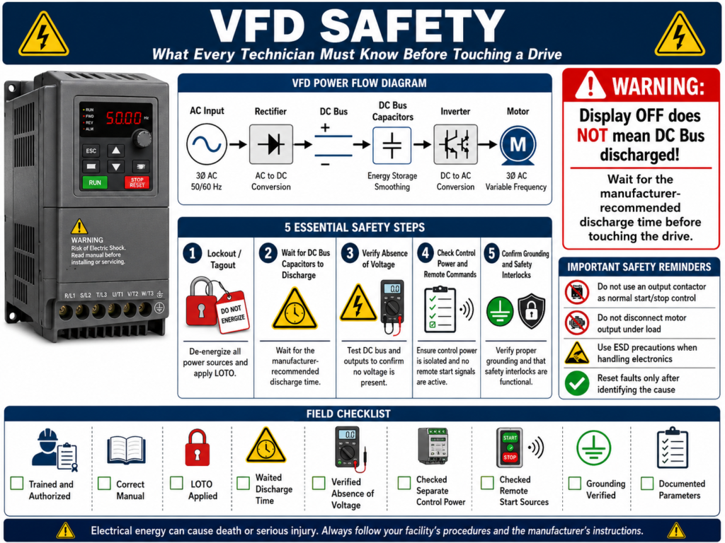
Inside the drive, incoming AC power is converted to DC. That DC energy is stored and smoothed by capacitors. These capacitors may remain charged after incoming power is removed.
The PowerFlex 4 manual specifically warns that the drive contains high-voltage capacitors that take time to discharge after mains supply is removed. It instructs technicians to isolate the mains supply from the line inputs and wait three minutes for the capacitors to discharge to safe voltage levels. It also warns that dark display LEDs do not mean the capacitors are discharged.
This is one of the most important VFD safety lessons:
Display OFF does not mean DC Bus discharged.Safe Mindset
Before touching anything inside a drive cabinet:
Power OFF
Lockout/Tagout applied
Stored energy discharged
Voltage verified with a properly rated meter
Manufacturer discharge time followed
Different VFD manufacturers and drive sizes may require different discharge times. Always verify the manual for the specific drive.
3. Lockout/Tagout Is Not Optional
Before working on a VFD, the energy source must be controlled.
A proper Lockout/Tagout process normally includes:
1. Identify all energy sources.
2. Notify affected personnel.
3. Stop the equipment using normal stop procedure.
4. Open the disconnect or breaker.
5. Apply lock and tag.
6. Release or wait for stored energy to dissipate.
7. Verify absence of voltage.
8. Perform the work.
9. Restore safely after checks are complete.
For VFDs, stored energy is especially important because the DC bus capacitors can remain charged after disconnecting input power.
Technician Note
Locking out only the PLC output or disabling the HMI start command is not the same as electrical isolation.
A VFD can have:
- Main power
- Control power
- Communication signals
- External 24 VDC
- Bypass circuits
- Remote start commands
- Fire/purge inputs
- Stored DC bus energy
Always understand the complete circuit before assuming the equipment is safe.
4. Verify Absence of Voltage
After Lockout/Tagout and waiting the required discharge time, a technician should verify absence of voltage using a properly rated meter.
This should include checking appropriate points such as:
[ ] Line side voltage
[ ] Load side voltage
[ ] DC bus voltage, if accessible and manufacturer procedure allows
[ ] Control power
[ ] External 24 VDC circuits
[ ] Stored energy points
Use the correct meter category rating for the environment.
Do not use a damaged meter, incorrect leads, or an unverified instrument.
Good Field Habit
Use the live-dead-live method when verifying absence of voltage:
1. Test meter on a known live source.
2. Test the circuit to verify absence of voltage.
3. Test meter again on a known live source.
This helps confirm that your meter was working before and after the test.
5. Control Power Can Be Separate from Main Power
Some VFD cabinets may have separate control power circuits.
This means the main drive input may be OFF, but other circuits may still be energized.
Examples:
- 24 VDC control power
- 120 VAC control transformer
- PLC I/O power
- Network communication modules
- HMI power
- Safety relay circuits
- Remote interlock wiring
- Bypass control circuits
A technician should never assume all control wiring is dead just because the main VFD disconnect is OFF.
Practical Example
A drive may be locked out on the 480 VAC input, but the PLC cabinet may still be sending 24 VDC to the drive digital input terminals.
That 24 VDC may not be the same shock hazard as 480 VAC, but it can still create unexpected commands, misleading troubleshooting readings, or equipment movement after power is restored.
6. Do Not Use the VFD Output Like a Normal Contactor Circuit
A VFD output is electronically generated by the inverter section. It is not the same as normal line power.
In most applications, the motor should be started and stopped by control commands to the drive, not by repeatedly opening and closing the motor output wiring.
VFDs are intended to be commanded by control input signals. It warns that installing a device that disconnects and reapplies output power to the motor should not be used as a normal control method. If such a device is required for something like Emergency Stop, auxiliary contacts should also disable the drive run command to help prevent drive damage.
Technician Note
Avoid this normal-control approach:
VFD Running → Open output contactor → Motor disconnected
VFD still commanded to run
This can create serious issues depending on the drive, load, and timing.
Better control philosophy:
Remove Run Command → Drive stops output → Then isolate if required by safety designFor safety circuits, always follow the machine’s safety design and applicable standards.
7. Emergency Stop and VFDs Must Be Designed Correctly
An Emergency Stop is not just a normal Stop button.
A normal Stop command usually tells the drive to stop according to its configured stop mode.
An Emergency Stop is part of a safety function and must be designed according to the risk assessment of the machine.
Possible VFD-related stop methods may include:
| Stop Type | Basic Meaning |
|---|---|
| Coast Stop | Drive output is removed and motor coasts |
| Ramp Stop | Drive decelerates motor using programmed decel |
| Controlled Stop | Drive stops in a controlled manner |
| Safe Torque Off | Drive torque-producing output is disabled, if supported |
| Output Isolation | Motor circuit isolated by contactors, when designed correctly |
Not every VFD has Safe Torque Off. Not every machine should rely on a ramp stop for safety. The correct method depends on the machine and safety requirements.
Important Point
A VFD fault or stop command is not automatically a safety-rated stop.
Safety functions must be designed, wired, verified, and maintained according to the required safety category/performance level for the machine.
8. Grounding Is a Safety and Reliability Requirement
Grounding is not optional.
The PowerFlex installation material states that the safety ground is required by code and must be connected to building steel, a ground rod, or ground bus. It also states that grounding points must comply with national and local industrial safety regulations and electrical codes.
The drive safety ground must be connected to the building ground system and that ground impedance must conform to code requirements. It also notes that the integrity of ground connections should be verified periodically.
Poor grounding can contribute to:
- Electrical shock hazards
- Nuisance faults
- Communication problems
- Noise on analog signals
- Ground fault issues
- Equipment damage
- Unstable operation
Grounding vs Common
A very important distinction:
Safety Ground ≠ DC CommonThe VFD training material notes that I/O terminals labeled “Common” are not safety grounds; they are shared source terminals.
This matters when troubleshooting digital inputs, analog signals, or 24 VDC circuits.
9. Shielding and Noise Must Be Handled Properly
VFDs create high-speed switching output waveforms. This can generate electrical noise.
Noise may affect:
- Analog inputs
- 4–20 mA signals
- 0–10 V signals
- Communication cables
- Encoder signals
- PLC inputs
- HMI communication
- Nearby instrumentation
The PowerFlex grounding section states that when shielded cable is used for control and signal wiring, the shield should be grounded at the source end only, not at the drive end. It also provides guidance for shield termination on motor cables.
Technician Note
When troubleshooting signal noise, check:
[ ] Motor cable shield termination
[ ] Analog signal shield termination
[ ] Separation between power and control wiring
[ ] Ground bonding
[ ] Loose grounds
[ ] VFD carrier frequency settings
[ ] Cable routing inside the panel
Noise problems are often wiring and grounding problems, not always bad devices.
10. Environmental Conditions Matter
A VFD must be installed in the correct environment.
Moisture, sunlight, and corrosive atmospheres can harm VFDs, and that manufacturers provide specifications for mounting and installing the drive.
Common environmental hazards include:
- Excessive heat
- Dust
- Conductive dust
- Metal shavings
- Moisture
- Washdown exposure
- Corrosive vapors
- Poor ventilation
- Blocked heatsinks
- Failed cooling fans
A dirty or overheated VFD can eventually fault or fail.
Practical Field Checks
Before blaming the drive, inspect:
[ ] Cabinet fans
[ ] Cabinet filters
[ ] Drive heatsink
[ ] Drive cooling fan
[ ] Airflow path
[ ] Ambient temperature
[ ] Water intrusion
[ ] Chemical exposure
[ ] Dust or metal particles
11. ESD Can Damage Drive Electronics
VFDs contain sensitive electronic parts.
The PowerFlex manual warns that the drive contains ESD-sensitive parts and assemblies. It states that static control precautions are required when installing, testing, servicing, or repairing the drive, and that component damage may result if ESD procedures are not followed.
This is especially important when handling:
- Control boards
- Option cards
- Communication adapters
- HIM modules
- Terminal boards
- Replacement electronics
Technician Note
When handling VFD electronics:
[ ] Use proper ESD precautions
[ ] Avoid touching circuit board components
[ ] Handle boards by the edges
[ ] Use ESD bags when storing boards
[ ] Avoid working on electronics in high-static areas
12. Branch Circuit Protection Must Be Correct
A VFD does not automatically replace all upstream protection requirements.
The PowerFlex manual states that the PowerFlex 4 does not provide branch short-circuit protection and should be installed with input fuses or an input circuit breaker. It also notes that national and local industrial safety regulations or electrical codes may determine additional requirements.
This is important during installation or replacement.
A replacement drive must not be installed without verifying:
[ ] Correct input voltage
[ ] Correct fuse or breaker size/type
[ ] Correct wire size
[ ] Correct grounding
[ ] Correct short-circuit current rating requirements
[ ] Correct enclosure/environment rating
13. Do Not Ignore the User Manual
One of the best safety habits is simple:
Check the manual before proceeding.Check the user manual before wiring or testing VFD circuits.
This matters because every manufacturer may have different requirements for:
- Discharge time
- Wiring terminals
- Grounding
- MOV removal
- Input protection
- Motor cable length
- Shielding
- Control wiring
- Sink/source selection
- Start/stop behavior
- Fault reset behavior
- Parameter backup procedure
14. Sink/Source Wiring Must Match the Drive Setup
Many VFDs allow digital inputs to be wired as sink or source.
If the SNK/SRC setup does not match the control wiring scheme, inputs may not work correctly or may behave unexpectedly.
The VFD start-up material highlights the need to verify that the SNK/SRC setup DIP switch matches the control wiring scheme before operation.
This is not only a functionality issue. It can become a safety issue if a run command or stop command does not behave as expected.
Technician Note
Before applying power or testing remote control:
[ ] Verify wiring diagram
[ ] Verify input common
[ ] Verify internal vs external supply
[ ] Verify sink/source setting
[ ] Verify stop input logic
[ ] Verify run command behavior
[ ] Verify fault reset input
15. A VFD Can Restart Unexpectedly If Configured That Way
Some VFDs include auto-restart or reset/run features.
This can be useful in certain process applications, but it can also be dangerous if technicians are not aware of it.
Before working near a motor or driven machine, verify whether the drive has:
- Auto restart enabled
- Run command maintained
- Network start command active
- Fire/purge override
- Remote interlock restart
- HOA Auto mode active
- Fault reset command from PLC
- Start on power-up behavior
The PowerFlex 400 material describes a Purge input that can start the drive at a programmed purge speed regardless of selected start source, and notes that Purge can operate whether the drive is running or stopped.
That is a great example of why technicians must understand the control strategy before working around equipment.
16. Do Not Reset Faults Blindly
A VFD fault is information.
Do not treat the reset button as the solution.
Before resetting, ask:
[ ] What is the fault code?
[ ] When did it occur?
[ ] During start, run, stop, or decel?
[ ] Was the motor overloaded?
[ ] Was there a voltage problem?
[ ] Was there a ground fault?
[ ] Was there a communication loss?
[ ] Did anyone change parameters?
[ ] Was the drive recently replaced?
Most VFDs monitor the condition or state of the drive and display changes on the integral keypad. It also notes that fault codes and fault indicators are used to notify the technician when a fault occurs.
17. Safety Before Backup or Parameter Work
Even when the task seems “only software,” safety still matters.
Before connecting a laptop, HIM, or communication tool, verify:
[ ] You are not exposing yourself to live terminals
[ ] Cabinet door access is permitted
[ ] PPE requirements are followed
[ ] Drive status is understood
[ ] Machine state is safe
[ ] Local/remote mode is understood
[ ] Start command source is understood
[ ] Backup/upload will not command motion
For example, using a HIM or DriveTools SP to upload parameters is normally a low-risk activity compared to wiring, but you may still be standing in front of energized equipment. The machine may also be capable of starting from remote commands.
VFD Safety Checklist for Technicians
Use this as a quick field checklist before touching a VFD:
[ ] Am I trained and authorized to perform this task?
[ ] Do I have the correct drive manual?
[ ] Do I understand the line side and load side?
[ ] Did I identify all energy sources?
[ ] Did I follow Lockout/Tagout?
[ ] Did I wait the manufacturer-required capacitor discharge time?
[ ] Did I verify absence of voltage with a properly rated meter?
[ ] Did I check for separate control power?
[ ] Did I check for external 24 VDC signals?
[ ] Did I verify grounding and bonding?
[ ] Did I identify remote start sources?
[ ] Did I verify local/remote/auto mode?
[ ] Did I check for auto-restart settings?
[ ] Did I check for fire/purge or safety override inputs?
[ ] Did I avoid disconnecting the VFD output under load?
[ ] Did I follow ESD precautions when handling electronics?
[ ] Did I document parameters before making changes?
Common VFD Safety Mistakes
Avoid these mistakes:
[ ] Assuming the display OFF means the drive is safe
[ ] Not waiting for DC bus capacitors to discharge
[ ] Not verifying absence of voltage
[ ] Forgetting separate control power
[ ] Treating DC common as safety ground
[ ] Using the output contactor as normal start/stop control
[ ] Ignoring auto-restart or maintained run commands
[ ] Resetting faults without investigating the cause
[ ] Not checking sink/source input configuration
[ ] Handling control boards without ESD precautions
[ ] Replacing a drive without checking fuses, grounding, and wiring
[ ] Ignoring the manufacturer manual
Simple Technician Explanation
A practical way to explain VFD safety is:
A VFD can be OFF, stopped, or faulted and still contain dangerous stored energy.
Always isolate, wait, verify, and understand the control strategy before touching the drive.
Or even shorter:
Stop is not safe.
Display off is not safe.
Locked out and verified is safe.
Final Thoughts
VFD safety is not only about avoiding electric shock. It is also about preventing unexpected motion, equipment damage, nuisance faults, and unsafe troubleshooting habits.
A good technician does not just ask:
How do I reset the drive?A good technician asks:
Is the equipment safe?
Where is the energy?
What is commanding the drive?
Are the capacitors discharged?
Is the motor isolated?
Is the control circuit still active?
What does the manual require?
Understanding VFD safety is the foundation for every other skill in this series. Before learning parameters, HIM navigation, DriveTools SP backups, troubleshooting, or PLC integration, the first priority is always the same:
Protect people first.
Protect equipment second.
Troubleshoot only when the system is in a known safe state.