8. Inductive Proximity Sensors: How They Detect Metal (8 of 15)
Introduction
Inductive proximity sensors are one of the most common sensors used in industrial automation. They are designed to detect metal objects without physical contact.
In PLC systems, inductive proximity sensors are commonly used for:
Cylinder position feedback
Metal part detection
Machine home position
Actuator extended/retracted confirmation
Sprocket or gear tooth detection
Conveyor stop position
Metal target verification
Indexing machine feedback
Unlike a limit switch, an inductive proximity sensor does not need to be physically touched by the target. The metal object only needs to enter the sensor’s detection field.
This makes inductive sensors very useful where mechanical contact would cause wear, impact, or adjustment problems.
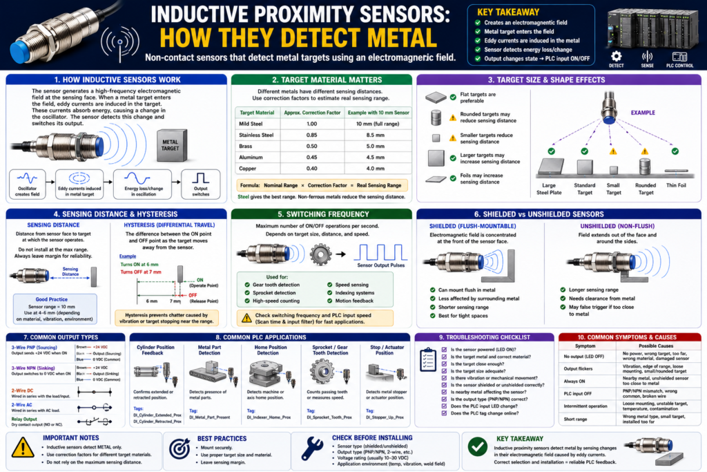
The Rockwell Automation sensor manual explains that inductive proximity sensors generate an electromagnetic field and detect eddy current losses created when metal targets enter that field. When the metal target gets close, it absorbs energy from the oscillator field, causing a change that the sensor electronics use to turn the output ON or OFF.
In simple words:
An inductive proximity sensor detects metal by sensing how the metal affects its electromagnetic field.What Is an Inductive Proximity Sensor?
An inductive proximity sensor is a non-contact sensor used to detect metal targets.
It is called inductive because it works using electromagnetic induction.
Basic concept:
Sensor creates electromagnetic field
↓
Metal target enters the field
↓
Eddy currents are induced in the metal
↓
Sensor detects energy loss/change
↓
Sensor output changes state
↓
PLC input turns ON or OFF
PLC tag examples:
DI_Cylinder_Extended_Prox
DI_Cylinder_Retracted_Prox
DI_Metal_Target_Detected
DI_Stopper_Home_Prox
DI_Index_Position_Prox
These are usually discrete inputs, meaning the PLC sees them as ON/OFF signals.
Why Inductive Sensors Are Important in PLC Systems
A PLC does not physically know where a cylinder, actuator, or machine part is. It needs feedback.
Example:
PLC command: Extend cylinder
Expected feedback: Cylinder extended proximity sensor turns ON
If the command is ON but the feedback never arrives, the PLC can generate a fault.
Example logic concept:
Cylinder_Extend_Command
AND NOT DI_Cylinder_Extended_Prox
AND Extend_Timer.DN
= Cylinder_Extend_Timeout_Fault
This type of feedback is what makes PLC logic more industrial and reliable.
The sensor confirms that the mechanical movement actually happened.
How an Inductive Sensor Detects Metal
Inside an inductive proximity sensor, there are several main parts:
Coil
Ferrite core
Oscillator
Signal detector
Output circuit
The sensor face produces a high-frequency electromagnetic field.
When there is no metal target near the sensor, the oscillator field is stable.
When a metal object enters the field, eddy currents are created in the metal target. These eddy currents absorb energy from the field. The sensor detects this energy loss and changes its output.
In technician language:
No metal near sensor = field is normal
Metal near sensor = field is disturbed
Sensor output changes
This is why inductive sensors are excellent for detecting metal, but not good for detecting cardboard, plastic, glass, or wood.
What Materials Can Inductive Sensors Detect?
Inductive sensors detect metal.
Common detectable materials include:
Mild steel
Stainless steel
Aluminum
Brass
Copper
Iron
Some metal alloys
However, not all metals are detected at the same distance.
This is a very important point.
The Rockwell manual explains that the target material has a large effect on sensing distance. It provides correction factors showing that mild steel has a correction factor of approximately 1.0, stainless steel 0.85, brass 0.50, aluminum 0.45, and copper 0.40.
That means:
A sensor rated for 10 mm on mild steel may not detect aluminum at 10 mm.Example using correction factor:
Nominal sensing distance = 10 mm
Target = aluminum
Correction factor = 0.45

Real approximate sensing range:
10 mm × 0.45 = 4.5 mm
So if you replace a steel target with aluminum, the sensor may stop detecting unless the distance is adjusted.
Target Correction Factors
Approximate correction factors from the manual:
| Target Material | Approximate Correction Factor |
|---|---|
| Mild steel | 1.0 |
| Stainless steel | 0.85 |
| Brass | 0.50 |
| Aluminum | 0.45 |
| Copper | 0.40 |
Practical meaning:
Steel gives the best sensing range.
Non-ferrous metals usually reduce the sensing range.
Important note:
Some special sensors are designed for ferrous-selective or nonferrous-selective detection. The manual notes that ferrous-selective sensors will not detect brass, aluminum, or copper, while nonferrous-selective sensors will not detect steel or ferrous-type stainless steels.
So always check the sensor datasheet.
Target Size and Shape Matter
Material is not the only factor.
The target’s size and shape also affect detection.
The Rockwell manual gives practical guidelines: flat targets are preferable, rounded targets may reduce sensing distance, smaller targets reduce sensing distance, larger targets may increase sensing distance, and foils may increase sensing distance.
Simple technician rules:
Flat metal target = better detection
Small target = shorter detection distance
Rounded target = may reduce sensing distance
Large target = may increase sensing distance
Thin foil = may behave differently
Example:
A flat steel plate is easier to detect than a small rounded bolt head.This matters when designing machine feedback. If the target is too small, too rounded, or too far away, the sensor may flicker or fail to turn ON.
Sensing Distance
Sensing distance is the distance from the sensor face to the metal target where detection occurs.
Example:
Sensor rated range: 8 mm
Target: mild steel
Installed distance: 5 mm
This is likely more reliable than installing the target at the full 8 mm edge of the range.
Better practice:
Do not install the target at the maximum sensing distance.
Leave margin.
Bad application:
Sensor range = 8 mm
Target distance = 8 mm
Better application:
Sensor range = 8 mm
Target distance = 4–6 mm, depending on material and vibration
The exact margin depends on sensor model, target material, mounting, vibration, temperature, and application.
Hysteresis in Inductive Sensors
Hysteresis is the difference between the sensor’s ON point and OFF point.
The Rockwell manual explains that hysteresis, also called differential travel, is needed to help prevent chattering when the sensor is exposed to shock, vibration, or when the target is stationary near the nominal sensing distance.
Simple example:
Target moves toward sensor:
Sensor turns ON at 6 mm

Target moves away:
Sensor turns OFF at 7 mm
The difference helps prevent rapid ON/OFF switching.
Without enough stable sensing margin, vibration can cause:
ON-OFF-ON-OFF-ON-OFFPLC effect:
Input chatter
False counts
Timer resets
Sequence instability
Faults appearing randomly
Technician rule:
If a proximity input flickers, check target distance, mounting stability, vibration, and hysteresis before blaming the PLC logic.Switching Frequency
Switching frequency tells you how fast the sensor can turn ON and OFF repeatedly.
The Rockwell manual defines switching frequency as the maximum speed at which a sensor can deliver discrete individual pulses as the target enters and leaves the sensing field. It depends on target size, target distance, target speed, and sensor type.
This matters for:
Gear tooth detection
Sprocket detection
High-speed counting
Speed sensing
Indexing applications
Small metal targets moving fast
Example:
A metal tooth passes the sensor.
The sensor output pulses ON/OFF.
The PLC counts pulses.
If the target moves too fast:
Sensor may miss pulses.
PLC count may be wrong.
Also remember:
Sensor speed is only one part of the system.
PLC scan time and input filter time also matter.
For high-speed applications, consider:
High-speed input module
Encoder module
Faster sensor
Better target geometry
Input filter adjustment
Hardware counter
Shielded vs Unshielded Inductive Sensors
Inductive sensors can be shielded or unshielded.
This is very important for mounting.
Shielded Sensors
A shielded sensor has construction that helps concentrate the electromagnetic field toward the front of the sensor face.
The Rockwell manual explains that shielded proximity sensors allow the electromagnetic field to be concentrated to the front of the sensor face, allowing them to be mounted flush in surrounding metal without causing false triggers.
In simple words:
Shielded sensor = can usually be flush-mounted in metal.Best for:
Tight machine spaces
Mounting in brackets
Flush mounting
Applications with metal around the sensor body
Unshielded Sensors
An unshielded sensor does not have the same metal band/shielding around the coil.
The sensing field spreads more around the sensor face and sides.
In simple words:
Unshielded sensor = longer range, but needs more clearance from surrounding metal.Best for:
Longer sensing range
Applications with enough mounting clearance
Targets farther from sensor face
Caution:
If mounted too close to surrounding metal, an unshielded sensor may false trigger or lose reliability.Shielded vs Unshielded Comparison
| Feature | Shielded Sensor | Unshielded Sensor |
|---|---|---|
| Mounting | Can usually mount flush in metal | Needs clearance from nearby metal |
| Sensing field | Concentrated forward | Larger field around face/sides |
| Range | Usually shorter | Usually longer |
| False trigger risk near metal | Lower | Higher if mounted incorrectly |
| Best use | Tight brackets, flush mounting | Longer range applications |
Practical rule:
If the sensor is mounted inside a metal bracket, use shielded/flush-mountable unless the datasheet says otherwise.Output Types: PNP, NPN, 2-Wire, 3-Wire
Inductive proximity sensors may come in different electrical output styles.
Common types:
3-wire PNP
3-wire NPN
2-wire DC
2-wire AC
Relay output
Analog versions for distance applications
IO-Link versions
For standard PLC discrete feedback, 3-wire DC PNP or NPN sensors are very common.
Typical 3-wire DC colors:
| Wire Color | Function |
|---|---|
| Brown | +24 VDC |
| Blue | 0 VDC |
| Black | Output signal |
PNP:
Black wire sends +24 VDC when sensor is ON.NPN:
Black wire switches toward 0 VDC/common when sensor is ON.Important:
Always match the sensor output type with the PLC input module wiring.Common PLC Applications
1. Cylinder Extended/Retracted Feedback
Application:
Pneumatic cylinder moves forward and back.
Proximity sensors confirm each end position.
PLC tags:
DI_Cylinder_Extended_Prox
DI_Cylinder_Retracted_Prox
PLC use:
Step complete feedback
Sequence transition
Timeout fault
HMI position status
Logic concept:
Cylinder_Extend_Command
AND DI_Cylinder_Extended_Prox
= Cylinder_Extend_Complete
Fault concept:
Cylinder_Extend_Command
AND NOT DI_Cylinder_Extended_Prox
AND Timer.DN
= Cylinder_Extend_Timeout_Fault
2. Metal Part Detection
Application:
Detect whether a metal part is present before a clamp, press, or transfer movement.PLC tag:
DI_Metal_Part_PresentPLC use:
Part present permissive
Reject missing part
Prevent machine cycle
Alarm operator
Logic concept:
Start_Cycle_Request
AND DI_Metal_Part_Present
AND No_Faults
= Cycle_Enable
3. Home Position Feedback
Application:
Detect when a rotating or sliding mechanism is at home position.PLC tag:
DI_Indexer_Home_ProxPLC use:
Home complete
Machine ready status
Sequence reset
Position confirmation
4. Sprocket or Gear Tooth Detection
Application:
Detect passing metal teeth for speed or counting.PLC tag:
DI_Sprocket_Tooth_ProxPLC use:
Speed calculation
Pulse counting
Jam detection
Motion feedback
Important:
Check switching frequency, target size, speed, and PLC input response.For faster motion, a normal digital input may not be enough.
Troubleshooting Inductive Proximity Sensors
When troubleshooting, do not only look at the PLC logic.
Start in the field.
Basic Checklist
1. Is the sensor powered?
2. Is the sensor LED ON when metal is present?
3. Is the target actually metal?
4. What type of metal is it?
5. Is the target close enough?
6. Is the target too small or rounded?
7. Is there vibration?
8. Is the sensor shielded or unshielded?
9. Is nearby metal affecting the sensor?
10. Is the output PNP, NPN, 2-wire, or 3-wire?
11. Does the PLC input LED change?
12. Does the PLC tag change online?
13. Is the logic using the correct tag?
Common Symptoms and Causes
| Symptom | Possible Cause |
|---|---|
| Sensor LED does not turn ON | No power, wrong target material, target too far |
| Sensor detects steel but not aluminum | Material correction factor reduces range |
| Input flickers | Target at edge of range, vibration, poor hysteresis margin |
| Sensor always ON | Nearby metal, wrong mounting, unshielded sensor too close to metal |
| PLC input does not turn ON | PNP/NPN mismatch, wrong common, broken wire |
| Counts are missing | Switching frequency too low, PLC input filter, scan time |
| Sensor works only sometimes | Loose mounting, target misalignment, temperature, contamination |
| Sensor damaged | Impact, wrong voltage, short circuit, harsh environment |
Practical Field Example
Problem:
Cylinder extended sensor flickers during operation.Possible investigation:
Sensor LED flickers when cylinder is extended.
PLC input flickers online.
Fault timer resets randomly.
Sequence sometimes advances, sometimes faults.
Possible causes:
Metal target is too far from sensor.
Cylinder vibrates at the extended position.
Sensor is at edge of sensing range.
Wrong target material.
Sensor is loose.
Mounting bracket moved.
Unshielded sensor is affected by nearby metal.
Corrective actions:
Move sensor closer within safe margin.
Secure sensor mounting.
Use proper metal target.
Check shielded vs unshielded sensor type.
Verify sensor alignment.
Add debounce only after fixing the physical issue.
Important:
Do not use PLC debounce to hide a poor sensor installation unless the physical problem has already been corrected as much as possible.Good PLC Tag Names
Use names that describe what the sensor proves.
Good examples:
DI_Cylinder_Extended_Prox
DI_Cylinder_Retracted_Prox
DI_Metal_Part_Present
DI_Indexer_Home_Prox
DI_Stopper_Up_Prox
DI_Stopper_Down_Prox
DI_Sprocket_Tooth_Prox
DI_Clamp_Closed_Prox
Avoid:
Prox1
Sensor2
Input_14
Metal_Sensor
A good tag name helps maintenance understand the machine faster.
Recommended Documentation Format
Example:
Tag Name:
DI_Cylinder_Extended_Prox

Sensor Type:
Inductive proximity sensor

Target:
Steel bracket mounted to cylinder slide

Signal Type:
24 VDC discrete input

Output Type:
PNP sourcing

Normal State:
ON when cylinder is fully extended

PLC Use:
Step complete feedback, HMI status, extend timeout fault

Troubleshooting:
Check sensor LED, target distance, bracket alignment, sensor power, black output wire, PLC input LED, and tag online.
Technician Mindset
When looking at an inductive proximity sensor, ask:
What metal is it detecting?
Is the target steel, stainless, aluminum, brass, or copper?
Is the target large enough?
Is the sensor installed within reliable sensing distance?
Is the sensor shielded or unshielded?
Is nearby metal affecting it?
Is vibration causing chatter?
Is the sensor output compatible with the PLC input?
Is this signal used as feedback, permissive, interlock, alarm, or fault?
This thinking helps you find the real issue faster.
Final Thoughts
Inductive proximity sensors are reliable and widely used in industrial automation, but they must be applied correctly.
They detect metal by generating an electromagnetic field and sensing the energy loss caused by eddy currents in the metal target.
They are excellent for:
Metal part detection
Cylinder position feedback
Machine home position
Actuator confirmation
Gear tooth or sprocket detection
But they are not universal sensors.
They do not detect non-metallic materials like cardboard, plastic, glass, or wood. Their sensing distance depends heavily on metal type, target size, target shape, mounting style, and surrounding metal.
The key takeaway is:
Inductive proximity sensors detect metal, but not all metals are detected equally.For PLC technicians, the most important rule is:
Good sensor application creates reliable PLC feedback.
Poor sensor application creates unstable machine behavior.
Before blaming the ladder logic, always verify the sensor, target, distance, mounting, wiring, and PLC input.