3. How to Read a Control Circuit Diagram (3 of 13)
Using Electrical Prints as a Troubleshooting Map
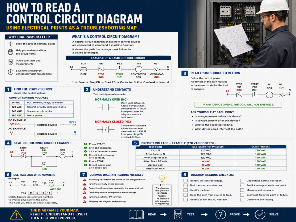
A control circuit diagram is one of the most important tools a technician can use when troubleshooting an electrical panel. Before replacing components, checking random terminals, or blaming the PLC, a technician should first understand how the circuit is supposed to work.
A good electrical diagram shows the path that voltage must follow for a device to energize. It helps the technician answer three important questions:
Where does the power start?
What devices must be closed or active?
Where is the load?
Where does the circuit return?
In industrial troubleshooting, the diagram is not just paperwork. It is the map.
The TSTrainer Lab Manual explains that the circuit diagram should be used as a guide to determine where voltage should be read, what voltage level should be expected, and when voltage should be present.
1. What Is a Control Circuit Diagram?
A control circuit diagram shows how electrical control devices are connected to command a machine function.
A simple control circuit may include:
Power source
Fuse or circuit breaker
Stop pushbutton
Start pushbutton
Relay coil
Contactor coil
Overload contact
Pilot light
Limit switch
Neutral or common return
The main purpose of the diagram is to show how control power flows through the circuit.
For example, a basic motor control circuit may work like this:
L1 → Fuse → Stop PB → Start PB → Contactor Coil → Overload Contact → L2 / NeutralWhen the circuit path is complete, the coil energizes.
When the path is open, the coil de-energizes.
That is the basic logic behind many electrical control circuits.
2. Start by Finding the Power Source
The first thing to identify is the power source.
Common control voltages include:
| Voltage | Common Use |
|---|---|
| 24 VDC | PLC inputs, sensors, relays, solenoids |
| 120 VAC | Traditional control circuits, coils, pilot lights |
| 240 VAC | Some control or small power circuits |
| 480 VAC | Three-phase motor power |
On a diagram, power may be shown as:
L1 and L2
L1 and Neutral
+24VDC and 0VDC
Control transformer secondary
Power supply output
Example:
L1 ───── Control Devices ───── Load ───── NFor DC control:
+24VDC ───── Control Devices ───── Load ───── 0VDCThe technician mindset is simple:
Before troubleshooting the device, prove that the correct voltage source exists.
If the source is missing, everything downstream will fail.
3. Identify the Load
The load is the device the circuit is trying to energize.
Examples of loads:
Relay coil
Contactor coil
Solenoid valve
Pilot light
Motor starter coil
PLC input
PLC output device
Alarm buzzer
Stack light
In a ladder-style control diagram, the load is usually shown near the right side of the rung.
Example:
L1 ── Stop PB ── Start PB ── Motor Starter Coil ── NHere, the Motor Starter Coil is the load.
In troubleshooting, the load is often the visible failure point.
Example:
Pilot light does not turn on.
Contactor does not pull in.
Solenoid valve does not actuate.
Relay does not energize.
That is why a strong method is to start at the failed load and work backward toward the source.
The manual reinforces this method: begin testing at the point of failure and systematically backtrack to the source of the problem.
4. Understand Normally Open and Normally Closed Contacts
Control diagrams use contacts to represent conditions.
The two most common are:
| Symbol Type | Meaning |
|---|---|
| Normally Open Contact | Open until activated |
| Normally Closed Contact | Closed until activated |
Normally Open Contact
A normally open contact does not pass power until the device is actuated.
Example:
Start Pushbutton
Relay auxiliary contact
PLC output contact
Limit switch used as a permissive
Simple representation:
──| |──Think of it as:
Must become TRUE to allow the circuit to continue.Normally Closed Contact
A normally closed contact passes power until the device is actuated.
Example:
Stop pushbutton
Overload contact
E-Stop contact
Fault contact
Limit switch used to stop motion
Simple representation:
──|/|──Think of it as:
Must remain healthy/closed to allow the circuit to continue.A very common motor control circuit uses both:
L1 ── Stop PB NC ── Start PB NO ── Contactor Coil ── OL NC ── NThe stop pushbutton and overload are normally closed because the circuit should open when the operator presses stop or when the overload trips.
5. Read the Circuit from Source to Return
A good habit is to read the control circuit like a sentence.
Example:
L1 → Stop PB → Start PB → Coil → Overload → NeutralThis means:
Power leaves L1, passes through the Stop pushbutton, passes through the Start pushbutton, energizes the coil, passes through the overload contact, and returns to neutral.
If any required device is open, the coil will not energize.
The technician should ask:
Is voltage present before the stop pushbutton?
Is voltage present after the stop pushbutton?
Is voltage present after the start pushbutton when pressed?
Is voltage present at the coil?
Is the return path/neutral present?
Each question becomes a meter test.
That is how the diagram becomes a troubleshooting map.
6. Follow the Rung Logic
Many control diagrams are drawn like ladder logic.
The left rail is usually the power side.
The right rail is usually the return side.
Example:
L1                                               N
|                                                |
|---[ STOP NC ]---[ START NO ]---( CR1 Coil )----|
|                                                |
To energize the coil:
STOP must be closed.
START must be pressed.
The coil must be good.
The return path must be complete.
When troubleshooting, do not look at the entire panel at once. Follow one rung at a time.
Ask:
What is this rung trying to energize?
What conditions must be true?
What component could interrupt the path?
Where should voltage appear?
7. Understand Seal-In or Holding Circuits
A common control circuit uses a seal-in contact to keep a relay or contactor energized after the start button is released.
Example:
L1 ── Stop PB NC ──+── Start PB NO ──+── CR1 Coil ── N
                   |                 |
                   +── CR1 NO -------+
How it works:
- The operator presses Start.
- The coil energizes.
- The CR1 auxiliary contact closes.
- The circuit now holds itself energized.
- The operator releases Start.
- The coil stays energized through the CR1 seal-in contact.
- Pressing Stop opens the circuit and drops out the coil.
This is one of the most important circuits for technicians to understand.
In troubleshooting, if the circuit starts only while holding the Start button but drops out when released, the seal-in path may be the issue.
Possible causes:
Bad auxiliary contact
Loose wire
Incorrect contact wiring
Relay not fully energizing
Broken terminal connection
Wrong contact used
8. Use the Diagram to Predict Voltage
Before measuring, predict what the meter should read.
Example:
A 120 VAC control circuit:
L1 ── Fuse ── Stop PB ── Start PB ── Relay Coil ── NIf the circuit is idle and Start is not pressed:
| Test Point | Expected Reading |
|---|---|
| L1 to N | 120 VAC |
| After fuse to N | 120 VAC |
| After Stop PB to N | 120 VAC |
| After Start PB to N | 0 VAC, unless Start is pressed |
| Coil hot side to N | 0 VAC, unless Start is pressed |
When Start is pressed:
| Test Point | Expected Reading |
|---|---|
| Coil hot side to N | 120 VAC |
| Across coil | 120 VAC |
| After Stop PB to N | 120 VAC |
| After Start PB to N | 120 VAC |
This is powerful because now your meter readings have meaning.
A random meter reading is just a number.
A predicted meter reading is evidence.
9. Know the Difference Between Measuring to Neutral and Across a Component
This is very important.
Measuring to Neutral
When measuring from a point to neutral, you are checking if voltage is available at that point.
Example:
Red lead: after fuse
Black lead: neutral
Expected: 120 VAC
This tells you power exists up to that point.
Measuring Across a Component
When measuring across a component, you are checking voltage drop.
Example:
Red lead: one side of Stop PB
Black lead: other side of Stop PB
If the Stop PB is closed, voltage across it should normally be close to 0 VAC.
If the Stop PB is open, you may read full control voltage across it.
This can help identify an open contact.
Simple rule:
A closed contact should drop little or no voltage.
An open contact may show full voltage across it.
10. Look for the Return Path
Many technicians focus only on the hot side of the circuit and forget the return path.
A load needs a complete circuit.
For AC control:
L1 → Load → NeutralFor DC control:
+24VDC → Load → 0VDCA missing neutral or 0V common can cause a device not to energize even when voltage is present on one side.
Example:
You measure 24 VDC on one side of a solenoid.
But the solenoid does not energize.
Possible issue:
Missing 0VDC common
Broken return wire
Loose terminal
Bad common fuse
Wrong reference point
Always troubleshoot both sides of the circuit.
11. Use Device Tags and Wire Numbers
Industrial diagrams often include tags and wire numbers.
Examples:
CR1
M1
OL1
PB1
LS1
PS1
FU1
TB1-14
I:1/0
O:2/3
These identifiers help you match the drawing to the real panel.
| Tag | Meaning |
|---|---|
| CR | Control Relay |
| M | Motor starter / contactor |
| OL | Overload |
| PB | Pushbutton |
| LS | Limit Switch |
| PS | Power Supply or Pressure Switch, depending on context |
| FU | Fuse |
| TB | Terminal Block |
| I | PLC Input |
| O | PLC Output |
When troubleshooting, use tags and wire numbers to avoid guessing which terminal belongs to which device.
Example:
Diagram shows wire 105 from CR1 contact to pilot light.
Panel terminal block shows wire 105.
Now you can physically trace that circuit.
This is exactly why good documentation matters.
12. Common Diagram Reading Mistakes
Avoid these common mistakes:
Assuming all contacts are shown in the energized state.
Ignoring normally closed contacts.
Forgetting the overload contact in the control circuit.
Confusing control voltage with motor voltage.
Following the wrong wire number.
Ignoring neutral or 0V common.
Assuming PLC output LED means field voltage is present.
Skipping the electrical print and guessing.
Most diagrams are drawn in the normal de-energized state unless noted otherwise.
That means a normally closed stop button is drawn closed because it is closed when not pressed. A normally open start button is drawn open because it is open when not pressed.
13. Practical Troubleshooting Example
Symptom:
Motor starter M1 does not energize when Start is pressed.Basic circuit:
L1 ── FU1 ── Stop PB NC ── Start PB NO ── OL NC ── M1 Coil ── NStep-by-step:
Step 1 — Verify source voltage
Measure L1 to N.
Expected: 120 VAC
If missing, troubleshoot power source.
Step 2 — Check after fuse
Measure after FU1 to N.
Expected: 120 VAC
If missing, check fuse or fuse holder.
Step 3 — Check after Stop PB
Measure after Stop PB to N.
Expected: 120 VAC
If missing, Stop PB circuit is open.
Step 4 — Press Start and check after Start PB
Measure after Start PB to N while pressing Start.
Expected: 120 VAC
If missing, Start PB is not closing or wiring is open.
Step 5 — Check after overload contact
Measure after OL contact to N.
Expected: 120 VAC when Start is pressed and overload is reset
If missing, overload contact may be open/tripped.
Step 6 — Check across M1 coil
Measure across M1 coil.
Expected: 120 VAC when commanded
If voltage is present and M1 does not pull in, suspect the coil or mechanical contactor issue.
14. Diagram Reading Checklist
Before troubleshooting, use this checklist:
[ ] Identify the control voltage.
[ ] Find the source and return.
[ ] Identify the load that should energize.
[ ] Trace the path from source to load.
[ ] Identify all NO and NC contacts in the path.
[ ] Understand the normal operation.
[ ] Predict voltage at each test point.
[ ] Measure with the correct meter setting.
[ ] Compare actual readings to expected readings.
[ ] Backtrack from the point of failure.
[ ] Document the finding and root cause.
This checklist helps keep troubleshooting methodical instead of random.
Final Thoughts
Reading a control circuit diagram is one of the most valuable skills an automation or maintenance technician can develop.
The diagram tells you what should happen.
The machine tells you what is actually happening.
The multimeter helps you prove where the difference is.
When you combine the three, troubleshooting becomes much more controlled.
A good technician does not simply open a panel and start guessing. A good technician reads the diagram, understands the expected operation, predicts voltage, tests with purpose, and follows the evidence