1. FANUC Teach Pendant Basics: How to Navigate Without Getting Lost
Introduction
For many automation technicians, the first challenge with a FANUC robot is not the robot arm itself. The real challenge is the Teach Pendant.
When a robot stops in production, the pendant is where you will check alarms, see the active program, find the stopped line, check I/O signals, move the robot manually, and recover the cell safely.
This post is the first part of the FANUC Robot Technician Series, focused on practical plant-floor knowledge for technicians working with robots that pick, place, stack, palletize, or handle containers and boxes.
The goal is simple:
Learn how to use the FANUC Teach Pendant without getting lost.
1. What Is the FANUC Teach Pendant?
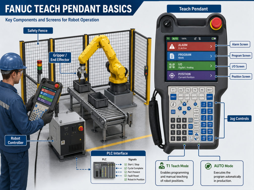
The Teach Pendant, also called the TP, is the handheld operator interface used to control, jog, program, troubleshoot, and recover a FANUC robot.
A typical FANUC robot system includes the robot arm, robot controller, teach pendant, end effector, safety fence or guarding, interlocked gates, I/O devices, and other peripheral equipment. FANUC safety documentation identifies the robot, controller, teach pendant, safety fence, interlocked gate, interlocking device, end effector, and workpieces as part of the overall robot system configuration.
In real plant terms, the pendant is where you go when:
- The robot is in alarm.
- The robot stopped mid-cycle.
- You need to see what program is running.
- You need to move the robot manually.
- You need to check inputs and outputs.
- You need to adjust a pick or place position.
- You need to recover the robot after a jam, bad pick, or collision.
2. Main Things You Need to Know First
Before editing programs or touching positions, you should become comfortable with these basic areas:
| Area | Why It Matters |
|---|---|
| Alarm Screen | Shows why the robot stopped |
| Program Screen | Shows what logic the robot is executing |
| Line Number | Shows exactly where the robot stopped |
| I/O Screen | Shows signals between robot, PLC, sensors, and gripper |
| Position Screen | Shows current robot position |
| Jog Controls | Allows manual movement |
| Coordinate System | Determines how the robot moves when jogging |
| Speed Override | Controls robot motion speed |
| Reset | Clears alarms after the real problem is corrected |
| Step Mode | Runs program one instruction at a time |
This post is not about advanced programming yet. It is about building navigation confidence.
3. FANUC Operating Modes: AUTO, T1, and T2
FANUC robots commonly use operating modes such as AUTO, T1, and sometimes T2, depending on the controller, region, configuration, and safety design.
| Mode | General Use |
|---|---|
| AUTO | Normal production operation |
| T1 | Teach/manual mode, normally used for slow-speed jogging and testing |
| T2 | Higher-speed test mode, available only on some systems |
| Remote / Local | Determines whether the robot is controlled from pendant, PLC, or external system |
T1 is normally the mode technicians use when they need to enter Teach Mode and move the robot manually. FANUC-related safety material describes AUTO and teach modes such as T1/T2, and emphasizes selecting the correct mode before teaching or entering the guarded area.
In a production cell, AUTO usually means the PLC, HMI, or cell control system is controlling the robot sequence. T1 means the technician or programmer is using the pendant for manual movement, testing, or recovery.
4. The Most Important Pendant Buttons
Different pendant models may look slightly different, but the core concepts are similar.
Common Buttons and Functions
| Button / Function | Purpose |
|---|---|
| RESET | Clears active alarms after the cause is corrected |
| SHIFT | Used with other keys for jogging and special actions |
| Deadman Switch | Enables motion in Teach Mode when held correctly |
| FWD | Runs the program forward, often used in step testing |
| BWD | Steps backward in some situations |
| STEP | Enables one-line-at-a-time execution |
| HOLD | Pauses robot execution |
| E-Stop | Emergency stop for unsafe conditions |
| COORD | Changes jog coordinate system |
| MENUS | Opens major menus |
| SELECT | Shows available robot programs |
| EDIT | Opens selected program for viewing or editing |
| DATA | Opens registers, position registers, and other data |
| I/O | Opens input/output screens |
| POSN | Shows current robot position |
The deadman switch is a critical safety function. FANUC safety documentation describes the deadman switch as an enabling device used when the teach pendant is enabled; motion is allowed only while the switch is held in the correct position.
Important practical note:
If you release the deadman, the robot stops. If you squeeze it too hard, the robot may also stop. It usually has a middle “enabled” position.
5. First Skill: Reading the Alarm Screen
When the robot stops, do not start pressing RESET repeatedly.
First, read the alarm.
What to Look For
On the alarm screen, identify:
- Alarm code
- Alarm text
- Active alarm or historical alarm
- Time of alarm
- Whether the same alarm returns after reset
- Whether the alarm is safety, servo, motion, program, I/O, or system related
Typical alarm categories may include:
| Alarm Type | Possible Meaning |
|---|---|
| SRVO | Servo, motion, safety, or axis-related issue |
| MOTN | Motion not allowed or motion error |
| INTP | Program/interpreter issue |
| SYST | System issue |
| TPIF | Teach pendant/interface issue |
| Safety Alarm | Gate, E-Stop, fence, scanner, enabling device |
| Collision Guard | Robot detected abnormal force or impact |
| Overtravel | Axis moved beyond allowed limit |
Technician Rule
Do not reset blindly.
Use this order:
1. Read the exact alarm.
2. Identify the alarm type.
3. Check if the cause is still present.
4. Correct the real problem.
5. Then press RESET.
A robot alarm is information. Treat it like a PLC fault code or VFD fault code.
6. Second Skill: Finding the Active Program
When the robot stops, you need to know what program it was running.
Go to the program area and identify:
- Program name
- Current line number
- Motion instruction
- Wait instruction
- I/O instruction
- Called subprogram
A basic FANUC program may look like this:
1: UFRAME_NUM=1 ;
2: UTOOL_NUM=2 ;
3: J P[1] 50% FINE ;
4: L P[2] 500mm/sec CNT50 ;
5: DO[10]=ON ;
6: WAIT DI[5]=ON ;
7: L P[3] 250mm/sec FINE ;
What This Means
| Line | Meaning |
|---|---|
UFRAME_NUM=1 | Active user frame |
UTOOL_NUM=2 | Active tool frame |
J P[1] | Joint move to position P[1] |
L P[2] | Linear move to position P[2] |
DO[10]=ON | Turns on an output |
WAIT DI[5]=ON | Waits for an input to turn on |
If the robot is stopped on a WAIT DI[x]=ON, it may not be a robot problem. It may be waiting for a signal from the PLC, sensor, gripper, vacuum switch, or safety system.
7. Third Skill: Understanding the I/O Screen
For technicians, the I/O screen is extremely important.
A lot of “robot faults” are really missing signals.
Common Robot Inputs
These are signals coming into the robot:
| Robot Input | Possible Meaning |
|---|---|
| Part Present | Box/container is ready |
| Gripper Opened | Tool is confirmed open |
| Gripper Closed | Tool is confirmed closed |
| Vacuum OK | Product is held |
| Safe To Pick | PLC says area is clear |
| Conveyor Ready | Conveyor is in position |
| Reset Request | PLC or HMI requests fault reset |
| Cycle Start | Start signal from PLC |
| Program Select | PLC selects robot program or recipe |
Common Robot Outputs
These are signals leaving the robot:
| Robot Output | Possible Meaning |
|---|---|
| Robot Ready | Robot is ready for cycle |
| Robot Running | Robot is executing |
| Robot Faulted | Robot has an active fault |
| Robot Home | Robot is at home position |
| Pick Complete | Pick operation completed |
| Place Complete | Place operation completed |
| Gripper Open Command | Command to open tool |
| Gripper Close Command | Command to close tool |
| Vacuum On | Command to activate vacuum |
Practical Example
Robot stopped at:
WAIT DI[12]=ONDI[12] could be:
DI[12] = Vacuum_OKIf Vacuum_OK is OFF, the robot may be waiting because:
- Vacuum cup is damaged.
- Air pressure is low.
- Box is not sealed.
- Vacuum sensor is misadjusted.
- Solenoid did not energize.
- Hose is leaking.
- Product is not in the correct position.
The robot is not always the root cause. The pendant helps you prove what the robot is waiting for.
8. Fourth Skill: Checking Robot Position
The position screen shows where the robot currently is.
You may see values such as:
X = 1250.500
Y = 840.200
Z = 350.000
W = 180.000
P = 0.000
R = 90.000
Or joint values such as:
J1 = 10.000
J2 = -25.000
J3 = 40.000
J4 = 0.000
J5 = 90.000
J6 = 180.000
Cartesian Position
Cartesian position usually uses:
| Axis | Meaning |
|---|---|
| X | Forward/back or cell direction depending on frame |
| Y | Left/right depending on frame |
| Z | Up/down depending on frame |
| W | Wrist rotation |
| P | Pitch |
| R | Roll |
Joint Position
Joint position shows the angles of each robot axis:
| Joint | Meaning |
|---|---|
| J1 | Base rotation |
| J2 | Shoulder |
| J3 | Elbow |
| J4 | Wrist rotation |
| J5 | Wrist bend |
| J6 | Tool rotation |
For troubleshooting, joint position helps you understand the robot posture. Cartesian position helps when adjusting pick/place locations.
9. Fifth Skill: Jogging the Robot Safely
Jogging means manually moving the robot with the pendant.
Before jogging:
1. Confirm the cell is safe.
2. Use Teach Mode / T1.
3. Hold the deadman correctly.
4. Lower the speed override.
5. Know your coordinate system.
6. Move slowly.
7. Watch the tool, not only the robot arm.
8. Keep clear of pinch points.
Coordinate Systems
The pendant can jog in different coordinate modes.
| Jog Mode | Meaning |
|---|---|
| Joint | Moves individual robot axes |
| World | Moves relative to the robot/world coordinate system |
| Tool | Moves relative to the tool direction |
| User | Moves relative to a defined work area or fixture |
| Jog Frame | Custom jogging frame on some systems |
Practical Recommendation
For beginners:
- Use Joint to get out of awkward positions.
- Use World/User when you need simple X/Y/Z movement.
- Be careful with Tool, because Z may follow the tool direction, not straight up/down in the cell.
10. Sixth Skill: Speed Override
The speed override controls how fast the robot moves.
When recovering from alarms or adjusting positions, use low speed.
Example:
Speed Override = 5% or 10%Do not jog at high speed near:
- Product
- Conveyor
- Gripper
- Fence
- Pallet
- Stacker
- Machine frame
- Operators
- Sensors
- Air lines
A small movement at the wrong speed can cause a crash.
11. Seventh Skill: STEP Mode
STEP mode allows the technician to run the robot program one instruction at a time.
This is very useful after:
- Alarm recovery
- Position adjustment
- Bad pick
- Bad place
- Jam recovery
- Program troubleshooting
Why STEP Mode Matters
Instead of letting the robot run the full cycle, you can observe each instruction.
Example:
1: Move to approach
2: Open gripper
3: Move to pick
4: Close gripper
5: Wait for grip confirmation
6: Move up
7: Move to place
This helps you see exactly where the problem happens.
12. Common Beginner Mistakes
Mistake 1 — Pressing RESET Without Reading the Alarm
RESET does not fix the problem. It only clears the alarm if the condition is gone.
Mistake 2 — Moving in the Wrong Coordinate System
The robot may move in an unexpected direction if you are in Tool instead of World/User.
Mistake 3 — Editing a Position Without Writing Down the Original
Always record the original values before changing anything.
Mistake 4 — Confusing Program Fault With I/O Wait
If the robot is waiting for an input, the issue may be the PLC, sensor, gripper, or pneumatic system.
Mistake 5 — Testing in AUTO Too Soon
After recovery or position changes, test slowly in Teach/STEP mode first.
13. Basic Pendant Navigation Checklist
Use this when you approach a stopped robot.
1. Check if the area is safe.
2. Look at the pendant alarm screen.
3. Write down the alarm code and message.
4. Check the active program.
5. Check the current line number.
6. Identify if the robot stopped on a motion, WAIT, CALL, or I/O instruction.
7. Check relevant DI/DO signals.
8. Check gripper, vacuum, air pressure, and product position.
9. Reset only after correcting the cause.
10. Jog slowly if manual recovery is required.
11. Use STEP mode before returning to AUTO.
14. Real Plant Example: Robot Waiting for Box Confirmation
Situation:
The robot picks a box from a conveyor, but the cycle stops before picking.
On the pendant, the program shows:
WAIT DI[20]=ONDI[20] is labeled:
Box_In_PositionThe signal is OFF.
Possible causes:
- Photo eye is dirty.
- Box is not fully against the stop.
- Conveyor did not index.
- PLC did not send the ready signal.
- Sensor cable is damaged.
- Input mapping is wrong.
- Mechanical guide is misaligned.
Correct troubleshooting path:
1. Check DI[20] on robot pendant.
2. Check the physical sensor.
3. Check sensor LED.
4. Check PLC input.
5. Check conveyor position.
6. Check box alignment.
7. Correct the cause.
8. Reset and test in STEP.
This is how a technician avoids guessing.
15. What You Should Practice First
Before changing any positions, practice these pendant navigation tasks:
1. Open the alarm screen.
2. Find the active alarm.
3. Open the program list.
4. Find the active program.
5. Find the current line.
6. Open the I/O screen.
7. Search DI and DO signals.
8. Open the position screen.
9. Change jog coordinate mode.
10. Change speed override.
11. Enable STEP mode.
12. Jog slowly in Joint mode.
13. Jog slowly in World or User mode.
The goal is not to become a programmer on day one. The goal is to stop being lost when the robot stops.
Conclusion
The FANUC Teach Pendant is the technician’s main tool for robot troubleshooting.
If you learn how to navigate the pendant, you can quickly answer the most important questions during downtime:
- What alarm is active?
- What program was running?
- What line stopped?
- Is the robot waiting for a signal?
- Is the problem robot, PLC, sensor, gripper, air, or product position?
- Can the robot be recovered safely?
Before learning advanced programming, master the basics:
Alarm → Program → Line → I/O → Position → Jog → STEP → RecoverThat sequence alone can solve many real production problems.