5. Troubleshooting When Nothing Works (5 of 13)
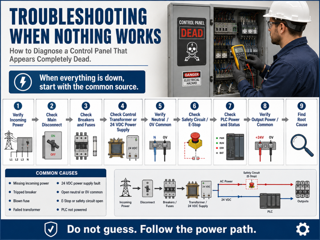
How to Diagnose a Control Panel That Appears Completely Dead
One of the most common troubleshooting situations in an electrical control panel is this:
Nothing works.
No lights.
No relay response.
No motor starter.
No PLC output activity.
No machine function.
When this happens, the technician must avoid guessing. Do not start by replacing relays, pushbuttons, contactors, PLC cards, or field devices.
When everything is down, the problem is usually not one individual device. The problem is often something common to the entire control system.
That common point may be:
Main disconnect
Circuit breaker
Control fuse
Control transformer
24 VDC power supply
Neutral or 0V common
Emergency stop circuit
Safety relay
Control power distribution
Loose incoming power terminal
When the work order states that “nothing is working,” the logical place to begin troubleshooting is the power source of the system, then verify the breaker and start checking voltage at test points.
1. Understand the Symptom: Is It Really “Nothing Works”?
Before opening the panel, define the symptom clearly.
Ask:
Is the entire machine dead?
Is only one section dead?
Is the HMI on?
Is the PLC powered?
Are any stack lights on?
Are any VFDs powered?
Are any relays energized?
Are any input LEDs changing?
Is the issue control power or motor power?
This matters because “nothing works” may mean different things depending on who reports it.
For example:
| Operator Says | Technician Should Verify |
|---|---|
| “The machine is dead” | Is the HMI off, PLC off, or only outputs off? |
| “The motor will not start” | Is only the motor down or is control power missing? |
| “No buttons work” | Are inputs reaching the PLC? |
| “No outputs work” | Is PLC output/common power missing? |
| “Panel has no power” | Is incoming voltage actually missing? |
A good technician translates the symptom into a testable condition.
2. Start with the Common Source
If multiple devices are not working, begin with what they have in common.
A basic control panel power path may look like this:
Incoming Power
      ↓
Main Disconnect
      ↓
Breaker / Fuse
      ↓
Control Transformer or 24 VDC Power Supply
      ↓
Control Power Distribution
      ↓
Relays / PLC / Inputs / Outputs / Pilot Lights
If nothing works, start upstream.
Do not start at a single pilot light, relay, or solenoid unless only that device failed.
The troubleshooting mindset is:
If one device fails, start at that device.
If everything fails, start at the source.
3. Verify Incoming Power
The first electrical question is:
Is power actually entering the panel?Depending on the system, this may be:
480 VAC three-phase
240 VAC
120 VAC
24 VDC
For a three-phase panel, verify line-to-line voltage:
L1-L2
L2-L3
L1-L3
For a 120 VAC control panel, verify:
L1 to NeutralFor a 24 VDC system, verify:
+24VDC to 0VDCIf incoming power is missing, the problem may be outside the panel:
Upstream disconnect off
Facility breaker tripped
Blown upstream fuse
Loose feed conductor
Power outage
Bad power distribution connection
Do not continue troubleshooting downstream until the source is proven.
4. Check the Main Disconnect and Breakers
A panel can appear dead because the disconnect is open or a breaker is tripped.
Check:
Main disconnect position
Breaker handle position
Tripped breaker indication
Fuse status
Line side voltage
Load side voltage
A very useful test is comparing line side and load side voltage.
Example:
| Test Location | Expected Result |
|---|---|
| Line side of breaker | Correct incoming voltage |
| Load side of breaker | Correct voltage when breaker is ON |
| Line side has voltage, load side does not | Breaker open/tripped/failed |
| Both sides have no voltage | Problem is upstream |
This helps you prove whether the issue is before or after the protection device.
5. Check the Control Transformer
Many panels use a control transformer to step down voltage.
Example:
480 VAC primary → 120 VAC secondaryIf the transformer secondary is missing, the entire 120 VAC control circuit may be dead.
Check:
Primary voltage into transformer
Secondary voltage out of transformer
Primary fuses
Secondary fuse
Transformer wiring
Loose terminals
Burn marks or smell
Basic logic:
Primary voltage present + no secondary voltage = possible transformer problem
No primary voltage = problem upstream
Secondary voltage present + control circuit dead = problem downstream
A control transformer is a common source point. If it fails, many devices may stop working at the same time.
6. Check the 24 VDC Power Supply
Modern automation panels often depend heavily on 24 VDC.
The 24 VDC power supply may feed:
PLC inputs
PLC outputs
Sensors
Photo eyes
Proximity switches
Solenoid valves
Control relays
Analog instruments
Network devices
HMI or panel devices
Check:
AC input to power supply
24 VDC output
Power supply status LED
DC OK contact if used
Output fuse or breaker
0V common connection
Load short or overload condition
A power supply can shut down because of a shorted sensor, damaged cable, overloaded output, or failed internal electronics.
Important:
Do not only measure +24VDC.
Also verify 0VDC common.
A missing common can make the system appear dead even if +24VDC is present.
7. Check Fuses Correctly
A blown fuse is common, but do not stop there.
A fuse may be the immediate fault, but not the root cause.
Check:
Voltage before the fuse
Voltage after the fuse
Fuse holder condition
Correct fuse rating
Signs of heat
Loose fuse clips
Shorted downstream device
Example:
120 VAC before fuse
0 VAC after fuse
This indicates an open fuse or bad fuse holder.
But the next question should be:
Why did the fuse open?Possible root causes:
Shorted solenoid coil
Damaged cable
Water inside junction box
Wrong fuse size
Loose terminal causing heat
Failed power supply
Shorted sensor
Miswired circuit
The manual repeatedly warns that a quick fix may not completely solve the issue and that the root cause must be identified to prevent the problem from returning.
8. Check Neutral or 0V Common
A missing return path can shut down a control circuit.
For AC control:
L1 → Load → NeutralFor DC control:
+24VDC → Load → 0VDCTechnicians sometimes focus only on the hot side and forget the return path.
Common neutral/common problems:
Loose neutral terminal
Broken 0VDC common wire
Blown common fuse
Missing jumper
Corroded terminal block
Disconnected field common
Bad terminal strip connection
Example:
You measure 120 VAC at one side of a relay coil.
The relay does not energize.
Possible issue:
The neutral side is open.A complete circuit always needs both source and return.
9. Check the E-Stop and Safety Circuit
Sometimes the panel has power, but the machine still appears dead because the safety circuit is open.
Check:
E-stop buttons
Safety relay status
Guard door switches
Light curtains
Safety gate switches
Safety contactor feedback
Reset circuit
Safety relay outputs
A safety circuit may remove power from contactor coils, motor starters, pneumatic valves, or PLC output enable circuits.
Do not bypass safety devices as a normal troubleshooting method.
Instead, verify:
Which safety input is open?
Is the safety relay receiving power?
Is the safety relay reset?
Are safety outputs closed?
Is the machine in a safe restart condition?
A safety circuit fault may look like a dead machine, but the real issue may be a guard switch, E-stop, light curtain, or failed safety relay condition.
10. Check PLC Power and Mode
If the panel uses a PLC, verify:
PLC power LED
Run mode
Fault LED
I/O module status
Input LEDs
Output LEDs
Communication status
24 VDC input power
Output common power
Important distinction:
PLC powered does not mean field power is good.
PLC output LED ON does not always mean field device is energized.
PLC troubleshooting is different because the technician can monitor the control program in real time, but the repair still requires identifying and correcting the actual fault. It also notes that many PLC system problems are related to the input/output devices connected to the system.
If the PLC is on and logic is running, but nothing in the field operates, check:
Output power feed
Output module common
Output fuse
Field wiring
Terminal blocks
Interposing relays
Device coils
11. Use a Logical Testing Sequence
For a “nothing works” condition, use this order:
1. Verify incoming power.
2. Check main disconnect.
3. Check breakers and fuses.
4. Check control transformer or power supply.
5. Verify control voltage distribution.
6. Check neutral or 0V common.
7. Check safety circuit status.
8. Check PLC power and mode.
9. Check output power/common.
10. Verify machine response after correction.
This sequence moves from the broadest common source toward the control devices.
12. Practical Example: 120 VAC Control Circuit Dead
Symptom:
No pilot lights.
No relay response.
No contactor coil operation.
Expected control voltage:
120 VACStep-by-step:
Step 1 — Check L1 to Neutral
Expected: 120 VACIf missing, check incoming/control source.
Step 2 — Check line side of control fuse
Expected: 120 VACIf missing, problem is upstream.
Step 3 — Check load side of control fuse
Expected: 120 VACIf line side has voltage and load side does not, check fuse or fuse holder.
Step 4 — Check control circuit distribution terminal
Expected: 120 VACIf missing after the fuse, check wiring from fuse to terminal block.
Step 5 — Check neutral
Expected: solid neutral referenceIf the hot side is present but devices do not energize, check neutral return.
Step 6 — Check safety/control permissive
Expected: safety relay or master control relay healthyIf control voltage exists but downstream devices are disabled, check E-stop/safety circuit.
13. Practical Example: 24 VDC System Dead
Symptom:
Sensors are off.
PLC inputs do not change.
Solenoids do not energize.
No 24 VDC pilot lights.
Step-by-step:
Step 1 — Check AC input to power supply
Expected: correct AC input voltageIf missing, check upstream AC feed, breaker, fuse, or transformer.
Step 2 — Check 24 VDC output
Expected: approximately 24 VDCIf missing, check power supply status.
Step 3 — Check output fuse or DC breaker
Expected: 24 VDC on both sidesIf voltage exists before the fuse but not after, the fuse or DC breaker is open.
Step 4 — Check 0 VDC common
Expected: complete return pathIf +24VDC exists but field devices do not operate, verify the common wiring.
Step 5 — Isolate possible shorted loads
Disconnect downstream branches only under safe procedures.
Restore one branch at a time if appropriate.
Possible root causes:
Shorted sensor cable
Failed solenoid coil
Water in junction box
Incorrect wiring
Overloaded power supply
14. Common Causes When Nothing Works
| Area | Possible Cause |
|---|---|
| Incoming power | Upstream breaker off, missing phase, loose feed |
| Main disconnect | Off, failed contacts, mechanical issue |
| Breaker/fuse | Tripped breaker, blown fuse, poor fuse holder |
| Transformer | No primary, failed secondary, open fuse |
| 24 VDC supply | Failed supply, overload, shorted load |
| Neutral/common | Open neutral, missing 0VDC common |
| Safety circuit | E-stop pressed, guard open, safety relay not reset |
| PLC | No power, faulted controller, not in Run mode |
| Output power | Missing output common, blown output fuse |
| Wiring | Loose terminal, broken conductor, corrosion |
15. Technician Report Example
A professional report may look like this:
Symptom:
Machine would not start. No pilot lights or relay response.

Expected Operation:
120 VAC control power should feed control relays and pilot lights through FU1.

Observation:
Main disconnect was ON. PLC was powered. No 120 VAC control devices responded.

Testing:
Measured 120 VAC on line side of FU1.
Measured 0 VAC on load side of FU1.
Verified fuse was open after LOTO.
Inspected downstream circuit before replacement.

Finding:
FU1 was blown.

Correction:
Replaced FU1 with correct-rated fuse after inspecting circuit.

Root Cause:
Solenoid valve cable had damaged insulation near a moving bracket, causing intermittent short to ground.

Final Verification:
Control power restored. Pilot lights and relays responded normally. Cable was replaced and rerouted.
This type of documentation shows that the technician did more than replace a fuse. They found the cause.
16. Final Troubleshooting Checklist
[ ] Confirm the actual symptom.
[ ] Determine if one device failed or the whole system failed.
[ ] Verify incoming power.
[ ] Check main disconnect.
[ ] Check breakers and fuses.
[ ] Verify control transformer secondary voltage.
[ ] Verify 24 VDC power supply output.
[ ] Check neutral or 0V common.
[ ] Check safety relay and E-stop circuit.
[ ] Check PLC power, mode, and fault status.
[ ] Check output power/common if PLC outputs are not working.
[ ] Repair only after proper isolation and LOTO when required.
[ ] Verify operation after repair.
[ ] Find and correct the root cause.
[ ] Document findings.
Final Thoughts
When nothing works, do not troubleshoot the panel like a collection of random parts.
Troubleshoot it like a system.
Start with what all the failed devices have in common:
Power source
Protection devices
Control voltage
Neutral/common
Safety circuit
PLC power
Output power
A dead panel usually tells a story. The technician’s job is to follow the power path, prove where voltage exists, prove where it disappears, and then determine why the failure happened.
In the next post, we will cover:
Troubleshooting One Device That Does Not Work
That is where the method changes. If only one device fails while the rest of the panel works, we stop looking at the main source and start focusing on that specific branch circuit.