Faults vs Alarms in Ladder Logic: Industrial Door PLC Example
Introduction
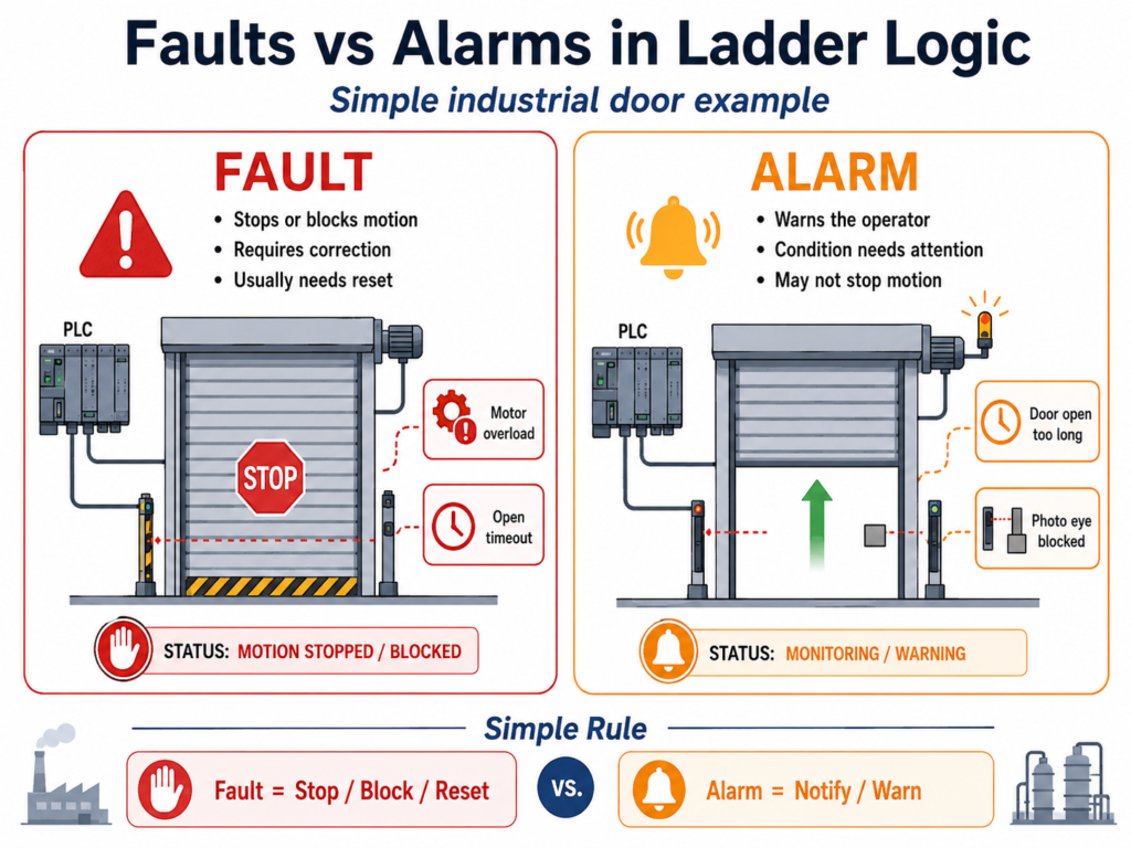
In industrial automation, one of the most important differences a technician must understand is the difference between a fault and an alarm.
At first, both may look similar because both indicate that something abnormal is happening. However, in a real PLC program, they should not be treated the same way.
A fault usually means the machine must stop or be prevented from running until the issue is corrected and reset.
An alarm usually means the operator needs to be informed about a condition, but the machine may not always need to stop.
This difference becomes very important when programming equipment such as an industrial door, conveyor, pump system, motor starter, or VFD-controlled machine.
In this post, we will use an industrial door as an example to explain how to structure status bits, alarms, faults, reset logic, acknowledge logic, permissives, interlocks, and output logic in ladder logic.
1. Basic Difference Between Status, Alarm, and Fault
A good industrial PLC program separates machine information into different categories.
Status
A status tells the operator or PLC what the machine is doing.
Examples:
Door_Fully_Open
Door_Fully_Closed
Door_Ajar
Door_Opening
Door_Closing
PhotoEye_Blocked
Status bits do not usually stop the machine by themselves. They simply describe the current condition.
Alarm
An alarm warns the operator that something needs attention.
Examples:
Alarm_Door_Open_Too_Long
Alarm_PhotoEye_Blocked
Alarm_Door_Ajar
Alarm_AutoClose_Delayed
An alarm may or may not stop the machine depending on the process.
For example, if a freezer door has been open too long, the system should notify the operator. However, that does not always mean the door motor has failed.
Fault
A fault indicates a condition that should stop or block machine operation.
Examples:
Fault_Motor_Overload_Latched
Fault_Open_Timeout_Latched
Fault_Close_Timeout_Latched
Fault_Command_Conflict_Latched
Fault_Limit_Switch_Conflict_Latched
Fault_Motor_Feedback_Latched
A fault normally requires a correction and then a reset before the machine can run again.
2. Simple Rule: Alarm vs Fault
A good way to decide whether something should be an alarm or a fault is to ask this question:
Should this condition stop or block machine motion?
If the answer is yes, it is probably a fault.
Fault = Stop / Block / Requires ResetShould this condition only notify the operator?
If the answer is yes, it is probably an alarm.
Alarm = Notify / Warn / May Continue3. Example Using an Industrial Door
For an industrial door, the PLC may control two directions:
Open Command
Close Command
The door may have field inputs such as:
DI_Open_PB
DI_Close_PB
DI_Stop_OK
DI_Safety_OK
DI_LS_Open_Position
DI_LS_Closed_Position
DI_PhotoEye_Clear
DI_Motor_OL_OK
DI_Motor_Running_FB
The PLC logic may generate internal bits such as:
Open_Request
Close_Request
Open_Permissive
Close_Permissive
Open_Interlock
Close_Interlock
Run_Open
Run_Close
Fault_Active
Alarm_Active
The goal is not just to make the door move. The goal is to make the door move safely, logically, and predictably.
4. Recommended PLC Structure
A clean ladder logic program should separate responsibilities into sections or subroutines.
Example structure:
SBR 1 - Input Buffering
SBR 2 - Status Logic
SBR 3 - Fault Logic
SBR 4 - Alarm Logic
SBR 5 - Command Logic
SBR 6 - Output Buffering
This structure makes troubleshooting much easier.
Instead of mixing everything in one place, each section has a clear purpose.
5. Status Logic
Status bits are useful because they give meaning to raw field inputs.
For example:
Door_Fully_Open = DI_LS_Open_Position
Door_Fully_Closed = DI_LS_Closed_Position
Door_Ajar = NOT DI_LS_Open_Position AND NOT DI_LS_Closed_Position
Conceptually:
If the open limit is ON, the door is fully open.
If the closed limit is ON, the door is fully closed.
If neither limit is ON, the door is somewhere between open and closed.
Example status tags:
Door_Fully_Open
Door_Fully_Closed
Door_Ajar
Door_Opening
Door_Closing
PhotoEye_Blocked
These bits can be displayed on the HMI or used in logic.
6. Fault Logic Concept
A fault should normally have two parts:
Fault Condition
Fault Latched
Fault Condition
The condition is the actual problem detected by the PLC.
Example:
Fault_Open_Timeout_ConditionThis may only be true while the problem exists.
Fault Latched
The latched fault stores the event until the operator or technician resets it.
Example:
Fault_Open_Timeout_LatchedThis is important because some faults may appear and disappear quickly. A latched bit allows the PLC and HMI to remember what happened.
7. Example Fault: Open Timeout
An open timeout fault happens when the PLC commands the door to open, but the door does not reach the open limit within the expected time.
This could indicate:
Motor issue
Gearbox issue
Door stuck
Broken chain or belt
Bad limit switch
VFD or starter problem
Mechanical obstruction
Rung 1 — Open Travel Timer
XIC Run_Open
XIO DI_LS_Open_Position
TON T_Open_Travel_Timer
Preset: 10 seconds
Purpose:
Start timing when the door is commanded to open and has not reached the open limit.Rung 2 — Open Timeout Condition
XIC T_Open_Travel_Timer.DN
OTE Fault_Open_Timeout_Condition
Purpose:
If the timer is done, the door took too long to open.Rung 3 — Latch Open Timeout Fault
XIC Fault_Open_Timeout_Condition
OTL Fault_Open_Timeout_Latched
Purpose:
Latch the open timeout fault until it is reset.8. Example Fault: Close Timeout
A close timeout fault is similar, but it monitors the closing motion.
Rung 1 — Close Travel Timer
XIC Run_Close
XIO DI_LS_Closed_Position
TON T_Close_Travel_Timer
Preset: 10 seconds
Rung 2 — Close Timeout Condition
XIC T_Close_Travel_Timer.DN
OTE Fault_Close_Timeout_Condition
Rung 3 — Latch Close Timeout Fault
XIC Fault_Close_Timeout_Condition
OTL Fault_Close_Timeout_Latched
This fault means the door failed to reach the closed position in time.
9. Example Fault: Motor Overload
If the motor overload or drive fault contact is wired into the PLC, the PLC should use it as a fault.
Assume:
DI_Motor_OL_OK = 1 means motor overload is healthy
DI_Motor_OL_OK = 0 means overload trip or drive fault
Rung — Motor Overload Fault
XIO DI_Motor_OL_OK
OTL Fault_Motor_Overload_Latched
Purpose:
If the overload OK signal is lost, latch a motor overload fault.This fault should stop and block motion until the overload condition is corrected.
10. Example Fault: Open and Close Command Conflict
A door should never be commanded to open and close at the same time.
This is a very important industrial check.
Rung — Command Conflict Fault
XIC Run_Open
XIC Run_Close
OTL Fault_Command_Conflict_Latched
Purpose:
If open and close commands are active at the same time, latch a command conflict fault.This can help detect:
Logic error
Duplicate output problem
Bad sequence design
Incorrect manual command handling
Even if the electrical circuit has reversing contactor interlocks, the PLC logic should still prevent conflicting commands.
11. Example Fault: Limit Switch Conflict
An industrial door should not be fully open and fully closed at the same time.
If both limit switches are active together, something is wrong.
Rung — Limit Switch Conflict Fault
XIC DI_LS_Open_Position
XIC DI_LS_Closed_Position
OTL Fault_Limit_Switch_Conflict_Latched
Possible causes:
Wiring issue
Wrong input mapping
Shorted signal
Bad limit switch
Sensor misalignment
Incorrect PLC tag assignment
This fault is very useful during troubleshooting because it detects an impossible door state.
12. Example Fault: Motor Feedback Failure
If the PLC sends a run command but does not receive motor running feedback, the motor may not actually be running.
Example causes:
Contactor failed to energize
VFD did not start
Starter problem
Overload open
Broken feedback wire
Control power issue
Rung 1 — Motor Feedback Delay
XIC Run_Open OR XIC Run_Close
XIO DI_Motor_Running_FB
TON T_Motor_FB_Delay
Preset: 2 seconds
Rung 2 — Latch Motor Feedback Fault
XIC T_Motor_FB_Delay.DN
OTL Fault_Motor_Feedback_Latched
Purpose:
If the PLC commands motion but does not see motor feedback after a short delay, latch a motor feedback fault.This makes the program more realistic and closer to actual industrial troubleshooting.
13. Fault Summary Bit
After creating individual fault bits, create one summary bit:
Fault_ActiveConcept:
Fault_Active =
    Fault_Motor_Overload_Latched
OR  Fault_Open_Timeout_Latched
OR  Fault_Close_Timeout_Latched
OR  Fault_Command_Conflict_Latched
OR  Fault_Limit_Switch_Conflict_Latched
OR  Fault_Motor_Feedback_Latched
In ladder, this is usually done with parallel branches feeding one output coil.
Example conceptual rung:
|--[XIC Fault_Motor_Overload_Latched]-------------|
|--[XIC Fault_Open_Timeout_Latched]---------------|
|--[XIC Fault_Close_Timeout_Latched]--------------|
|--[XIC Fault_Command_Conflict_Latched]-----------|----(OTE Fault_Active)
|--[XIC Fault_Limit_Switch_Conflict_Latched]------|
|--[XIC Fault_Motor_Feedback_Latched]-------------|
Important note:
Avoid using multiple OTE instructions to the same bit in different rungs. It is better to build the summary in one rung using parallel branches or use intermediate bits.
14. Using Fault_Active in Permissives and Interlocks
The Fault_Active bit should block door motion.
Example:
Motion_Allowed =
    DI_Stop_OK
AND DI_Safety_OK
AND NOT Fault_Active
Then use Motion_Allowed inside the open and close permissives.
Open Permissive
Open_Permissive =
    Motion_Allowed
AND NOT DI_LS_Open_Position
AND NOT Run_Close
Close Permissive
Close_Permissive =
    Motion_Allowed
AND NOT DI_LS_Closed_Position
AND NOT Run_Open
AND DI_PhotoEye_Clear
This keeps the logic clean.
Instead of repeating all fault conditions everywhere, the program uses one fault summary bit.
15. Alarm Logic Concept
Alarms are used to notify the operator.
Not every alarm needs to stop the machine.
Some alarms are informational. Others may delay or prevent certain automatic actions.
Common door alarms:
Alarm_Door_Open_Too_Long
Alarm_PhotoEye_Blocked
Alarm_Door_Ajar
Alarm_AutoClose_Delayed
16. Example Alarm: Door Open Too Long
This is a good alarm for a freezer door or production area door.
If the door remains open too long, the operator should know.
Rung 1 — Door Open Timer
XIC DI_LS_Open_Position
TON T_Door_Open_Too_Long
Preset: 60 seconds
Rung 2 — Alarm Door Open Too Long
XIC T_Door_Open_Too_Long.DN
OTE Alarm_Door_Open_Too_Long
This alarm does not necessarily mean the door motor failed. It means the door has remained open longer than expected.
In some applications, this could trigger:
HMI alarm
Pilot light
Horn
Message to operator
Auto-close sequence
Maintenance notification
17. Example Alarm: Photo Eye Blocked
The photo eye normally protects the closing motion.
If the photo eye is blocked, the door should not close.
This may be a status or alarm depending on the application.
Simple Photo Eye Alarm
XIO DI_PhotoEye_Clear
OTE Alarm_PhotoEye_Blocked
For many doors, this may be normal when a person or object passes through the doorway.
A better industrial version is to alarm only if the photo eye remains blocked too long.
Photo Eye Blocked Too Long Timer
XIO DI_PhotoEye_Clear
TON T_PhotoEye_Blocked_Delay
Preset: 10 seconds
Photo Eye Blocked Too Long Alarm
XIC T_PhotoEye_Blocked_Delay.DN
OTE Alarm_PhotoEye_Blocked_Too_Long
This avoids nuisance alarms.
18. Example Alarm: Door Ajar
A door is considered ajar when it is not fully open and not fully closed.
Door_Ajar =
    NOT DI_LS_Open_Position
AND NOT DI_LS_Closed_Position
A simple alarm may be:
XIC Door_Ajar
TON T_Door_Ajar_Delay
Preset: 15 seconds
Then:
XIC T_Door_Ajar_Delay.DN
OTE Alarm_Door_Ajar
This tells the operator that the door is sitting between limits for too long.
19. Alarm Summary Bit
Just like faults, alarms can have a summary bit:
Alarm_ActiveConcept:
Alarm_Active =
    Alarm_Door_Open_Too_Long
OR  Alarm_PhotoEye_Blocked_Too_Long
OR  Alarm_Door_Ajar
OR  Alarm_AutoClose_Delayed
Example:
|--[XIC Alarm_Door_Open_Too_Long]-------------|
|--[XIC Alarm_PhotoEye_Blocked_Too_Long]------|
|--[XIC Alarm_Door_Ajar]----------------------|----(OTE Alarm_Active)
|--[XIC Alarm_AutoClose_Delayed]--------------|
This can drive an HMI banner, alarm indicator, or stack light.
20. Reset vs Acknowledge
This is one of the most important concepts in industrial automation.
Reset
A reset is normally used for faults.
Reset means:
The issue has been corrected, and the operator wants to allow the machine to run again.A reset should not clear a fault if the fault condition is still present.
Acknowledge
An acknowledge is normally used for alarms.
Acknowledge means:
The operator has seen the alarm.Acknowledge does not always mean the condition has been corrected.
21. Fault Reset Logic
A safe reset should only be allowed when the machine is not moving.
Example:
Reset_Allowed =
    Reset_Faults_PB
AND DI_Stop_OK
AND DI_Safety_OK
AND NOT Run_Open
AND NOT Run_Close
Then each fault can be reset only if its condition is no longer present.
Reset Open Timeout Fault
XIC Reset_Allowed
XIO Fault_Open_Timeout_Condition
OTU Fault_Open_Timeout_Latched
Reset Close Timeout Fault
XIC Reset_Allowed
XIO Fault_Close_Timeout_Condition
OTU Fault_Close_Timeout_Latched
Reset Motor Overload Fault
XIC Reset_Allowed
XIC DI_Motor_OL_OK
OTU Fault_Motor_Overload_Latched
Reset Limit Switch Conflict Fault
XIC Reset_Allowed
XIO DI_LS_Open_Position OR XIO DI_LS_Closed_Position
OTU Fault_Limit_Switch_Conflict_Latched
Conceptually:
Do not reset the fault if the problem is still active.22. Alarm Acknowledge Logic
Alarms may be acknowledged separately from faults.
Example:
XIC Ack_Alarms_PB
OTU Alarm_Door_Open_Too_Long_Latched
For a more controlled design, only allow the alarm to clear if the condition is gone:
XIC Ack_Alarms_PB
XIO Alarm_Door_Open_Too_Long_Condition
OTU Alarm_Door_Open_Too_Long_Latched
This depends on the HMI and plant standard.
Some systems allow acknowledge while the condition remains active, but the alarm stays visible as active-unacknowledged or active-acknowledged.
23. Recommended Door Fault List
For a beginner-friendly but industrial-style door program, these faults are a good starting point:
| Fault Tag | Description | Stops Motion | Requires Reset |
|---|---|---|---|
Fault_Motor_Overload_Latched | Motor overload or drive fault | Yes | Yes |
Fault_Open_Timeout_Latched | Door failed to reach open limit | Yes | Yes |
Fault_Close_Timeout_Latched | Door failed to reach closed limit | Yes | Yes |
Fault_Command_Conflict_Latched | Open and close active together | Yes | Yes |
Fault_Limit_Switch_Conflict_Latched | Open and closed limits active together | Yes | Yes |
Fault_Motor_Feedback_Latched | Motor command without feedback | Yes | Yes |
24. Recommended Door Alarm List
These alarms are useful for operator awareness:
| Alarm Tag | Description | Stops Motion | Requires Reset |
|---|---|---|---|
Alarm_Door_Open_Too_Long | Door remained open too long | No | Optional |
Alarm_PhotoEye_Blocked_Too_Long | Photo eye blocked too long | Blocks close only | Optional |
Alarm_Door_Ajar | Door is between limits too long | No | Optional |
Alarm_AutoClose_Delayed | Auto-close is waiting or interrupted | No | No |
25. How Faults, Alarms, Permissives, and Interlocks Work Together
A clean control strategy may look like this:
Field Inputs
     ↓
Input Buffering
     ↓
Status Logic
     ↓
Fault Detection
     ↓
Fault Latching
     ↓
Alarm Logic
     ↓
Permissives / Interlocks
     ↓
Command Logic
     ↓
Output Buffering
     ↓
Physical Outputs
The relationship is important:
Faults affect permissives and interlocks.
Alarms inform the operator.
Status bits describe the machine.
Outputs should only energize when all logic is valid.
26. Example Final Motion Logic
Motion Allowed
Motion_Allowed =
    DI_Stop_OK
AND DI_Safety_OK
AND NOT Fault_Active
Open Permissive
Open_Permissive =
    Motion_Allowed
AND NOT DI_LS_Open_Position
AND NOT Run_Close
Close Permissive
Close_Permissive =
    Motion_Allowed
AND NOT DI_LS_Closed_Position
AND NOT Run_Open
AND DI_PhotoEye_Clear
Open Command
Open_Request
AND Open_Permissive
AND Open_Interlock
= Run_Open
Close Command
Close_Request
AND Close_Permissive
AND Close_Interlock
= Run_Close
Final Output Buffer
Run_Open
AND NOT Run_Close
AND NOT Fault_Active
= DO_Motor_Open
Run_Close
AND NOT Run_Open
AND NOT Fault_Active
AND DI_PhotoEye_Clear
= DO_Motor_CloseThe output buffer is the last logical protection before energizing the physical output.
27. Best Practices
1. Do not use raw inputs directly everywhere
Use input buffering.
Example:
Raw Input → Debounced/Buffered Input → Program LogicThis makes the program cleaner and easier to troubleshoot.
2. Separate status, alarm, and fault logic
Do not mix everything in one rung.
A structured program is easier to read and debug.
3. Latch important faults
Faults should usually remain active until reset.
This helps maintenance understand what happened.
4. Do not reset faults while the machine is moving
Reset should normally require:
No motion
Safety OK
Stop circuit OK
Fault condition corrected
5. Use fault summary and alarm summary bits
Summary bits make command logic cleaner.
Example:
Fault_Active
Alarm_Active
Motion_Allowed
6. Avoid duplicate OTE outputs
Do not drive the same output coil in multiple places unless the PLC platform and program structure are designed for it.
Use internal bits and one final output buffer rung.
7. Make alarms useful, not noisy
Too many nuisance alarms can cause operators to ignore real problems.
Use timers to avoid alarming on short, normal events.
Example:
Photo eye blocked for 1 second = normal
Photo eye blocked for 15 seconds = alarm
28. Final Thoughts
Understanding the difference between faults and alarms is a major step toward writing more professional ladder logic.
A simple machine can run with basic start/stop logic, but an industrial machine needs better structure.
A good PLC program should answer these questions:
What is the machine doing?
Is it safe to start?
Is it safe to continue?
Did something fail?
Should the operator be notified?
Should motion be blocked?
Can the fault be reset?
For an industrial door, the logic should be organized around:
Status
Permissives
Interlocks
Faults
Alarms
Reset
Acknowledge
Output Buffering
When these sections are built correctly, the program becomes easier to troubleshoot, safer to operate, and closer to what technicians see in real industrial control systems.