13. Replacing a VFD in the Field: Professional Technician Checklist (13 of 19)
Introduction
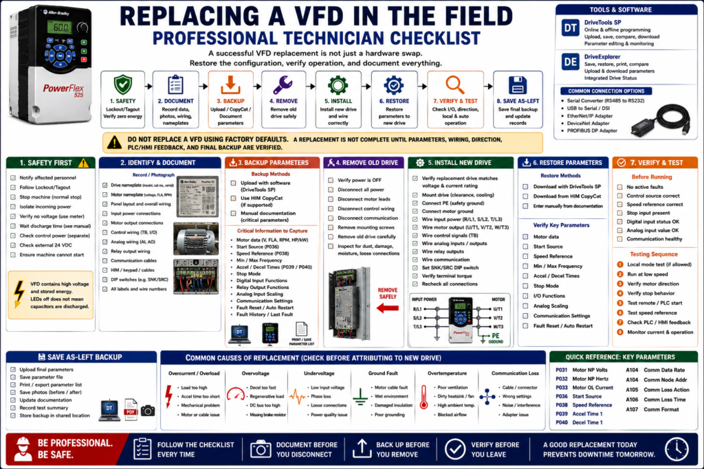
Replacing a Variable Frequency Drive in the field is not just a hardware swap.
A VFD controls a motor, but it also stores the configuration that makes the motor work correctly for the machine. If the replacement drive is installed with factory defaults, the motor may not start, may run at the wrong speed, may ignore PLC commands, may fault immediately, or may fail to provide the correct feedback to the HMI.
A professional VFD replacement requires a structured process:
Identify → Document → Backup → Replace → Restore → Verify → Test → SaveThe examples in this post use Allen-Bradley PowerFlex drives as a practical reference, but this checklist applies to most industrial VFDs regardless of manufacturer.
Why a VFD Replacement Must Be Planned
A VFD replacement can affect:
Motor protection
Motor direction
Start/stop control
Speed reference
Acceleration and deceleration
Stop mode
Analog scaling
Digital input functions
Relay output functions
Communication settings
Fault reset behavior
PLC/HMI feedback
Process performance
PowerFlex documentation shows that key parameters include motor nameplate data, start source, speed reference, stop mode, acceleration/deceleration, digital inputs, relay outputs, and communication settings. These parameters define how the drive behaves in the machine, so they must be captured before or during replacement whenever possible.
1. Start with Safety
Before touching the VFD, the first priority is safety.
A VFD contains high voltage and stored energy. The drive may also have separate control power, communication wiring, external 24 VDC, bypass circuits, or remote start commands.
The PowerFlex manual warns that drives contain high-voltage capacitors that take time to discharge after removing mains supply. It also states that dark display LEDs do not mean the capacitors have discharged, and that only qualified personnel should install, start up, or maintain the drive.
Safety Checklist
[ ] Notify affected personnel.
[ ] Stop the machine using the normal stop procedure.
[ ] Follow Lockout/Tagout.
[ ] Isolate incoming power.
[ ] Wait the manufacturer-required DC bus discharge time.
[ ] Verify absence of voltage with a properly rated meter.
[ ] Check for separate control power.
[ ] Check for external 24 VDC signals.
[ ] Check for bypass or alternate power paths.
[ ] Confirm the machine cannot start unexpectedly.
2. Identify the Existing Drive
Before removing anything, identify exactly what is installed.
Record:
[ ] Manufacturer
[ ] Drive family
[ ] Catalog number
[ ] Voltage rating
[ ] Output current rating
[ ] Horsepower / kW rating
[ ] Enclosure type
[ ] Firmware version, if available
[ ] Communication adapter type
[ ] HIM/keypad type
[ ] Serial number
Take a photo of the drive nameplate and any labels inside the panel.
Technician Note
Do not replace a drive based only on horsepower.
Verify:
Drive voltage rating
Drive output current rating
Motor FLA
Load type
Overload requirement
Communication requirements
Physical size and mounting
3. Identify the Motor
A replacement VFD must be matched to the motor.
Record motor nameplate data:
[ ] Motor voltage
[ ] Motor FLA
[ ] Motor frequency
[ ] Motor RPM
[ ] Motor horsepower / kW
[ ] Phase
[ ] Service factor
[ ] Insulation class
[ ] Duty
[ ] Wiring configuration
The PowerFlex troubleshooting guidance notes that unstable motor operation can be caused by incorrectly entered motor data and recommends correctly entering motor nameplate data into parameters such as motor volts, motor hertz, and motor overload current.
Important
If the motor is dual-voltage, verify how the leads are connected.
Example:
230/460 VAC motorThe motor lead configuration must match the voltage supplied by the VFD.
4. Document the Wiring Before Disconnecting
Before removing the old drive, take clear pictures.
Photo checklist:
[ ] Incoming power terminals
[ ] Motor output terminals
[ ] Ground connections
[ ] Control terminals
[ ] Digital input wiring
[ ] Analog input wiring
[ ] Relay output wiring
[ ] Communication cable
[ ] HIM/keypad cable
[ ] DIP switches such as SNK/SRC
[ ] Labels and wire numbers
[ ] Any jumpers
This is especially important if the drawings are outdated or missing.
The VFD installation material emphasizes verifying that all inputs are connected to the correct terminals and secure before applying power, and that SNK/SRC setup must match the control wiring scheme.
5. Backup the Parameters
A VFD backup should be completed before removal if the old drive still powers up.
Preferred backup methods:
1. Software upload
2. HIM CopyCat
3. Manual parameter documentation
PowerFlex 400 documentation states that DriveExplorer can save, restore, print, compare, edit, upload, and download parameter information, while DriveTools SP supports online/offline programming and parameter editing.
Backup Checklist
[ ] Upload parameter file with software if available.
[ ] Use HIM CopyCat if supported.
[ ] Save or print parameter list.
[ ] Record motor data parameters.
[ ] Record start source.
[ ] Record speed reference.
[ ] Record min/max frequency.
[ ] Record accel/decel time.
[ ] Record stop mode.
[ ] Record digital input functions.
[ ] Record relay output functions.
[ ] Record analog input settings.
[ ] Record communication settings.
[ ] Record fault history.
The VFD training exercises repeatedly instruct the technician to test operation and record all parameters, reinforcing that parameter documentation is part of proper VFD work.
6. Review Fault History Before Removing the Drive
If the old drive can power up, check the fault history before replacing it.
Record:
[ ] Last fault code
[ ] Fault frequency
[ ] Fault condition
[ ] Whether it happened during start, run, or stop
[ ] Output current at failure, if available
[ ] DC bus voltage at failure, if available
[ ] Communication status
The VFD troubleshooting material explains that VFDs monitor their condition and show state changes on the keypad. It also notes that fault codes and fault indicators are used to notify the technician when a fault occurs.
Why This Matters
The old drive may not be the root cause.
Possible real causes:
Bad motor
Ground fault
Mechanical overload
Incorrect deceleration
Poor ventilation
Loose input power
Communication issue
Analog signal loss
Wrong parameter setting
Replacing a drive without understanding the fault may result in the new drive faulting immediately.
7. Verify the Replacement Drive
Before installing the replacement, compare it to the original.
[ ] Same manufacturer or approved equivalent
[ ] Correct voltage rating
[ ] Correct output current rating
[ ] Correct horsepower / kW range
[ ] Correct enclosure type
[ ] Correct control voltage compatibility
[ ] Correct communication adapter
[ ] Correct firmware compatibility, if required
[ ] Correct physical mounting
[ ] Correct braking option, if used
[ ] Correct safety features, if used
Technician Note
A replacement drive may be “close” but still not correct.
Examples:
Wrong input voltage
No braking transistor
Different communication adapter
Different I/O terminal layout
Different parameter numbers
Different firmware behavior
Different enclosure rating
Always verify the manual and plant standard.
8. Install the Replacement Drive
After safety procedures and documentation are complete, install the replacement drive.
Installation checklist:
[ ] Mount the drive correctly.
[ ] Maintain required clearance.
[ ] Keep airflow path open.
[ ] Verify panel is clean.
[ ] Remove metal shavings or debris.
[ ] Connect PE safety ground.
[ ] Connect motor ground.
[ ] Connect input power.
[ ] Connect output motor leads.
[ ] Connect control wiring.
[ ] Connect analog wiring.
[ ] Connect relay outputs.
[ ] Connect communication wiring.
[ ] Verify terminal torque.
[ ] Verify all jumpers and DIP switches.
The PowerFlex 4 manual states that most start-up difficulties are caused by incorrect wiring and that wiring instructions should be read and understood before installation.
9. Restore the Parameters
After wiring is complete, restore the configuration.
Methods:
[ ] Download saved file using software.
[ ] Download from HIM CopyCat.
[ ] Manually enter documented parameters.
After restoring, do not assume the job is complete.
Verify these critical values:
[ ] Motor rated voltage
[ ] Motor rated current / FLA
[ ] Motor rated frequency
[ ] Motor RPM, if used
[ ] Start Source
[ ] Speed Reference
[ ] Stop Mode
[ ] Minimum Frequency
[ ] Maximum Frequency
[ ] Accel Time
[ ] Decel Time
[ ] Digital Input assignments
[ ] Relay Output assignments
[ ] Analog Input scaling
[ ] Communication settings
[ ] Fault reset method
[ ] Auto restart settings
PowerFlex troubleshooting guidance for a drive that does not start or respond to speed changes points technicians to check parameters such as Start Source, Speed Reference, Control Source, Digital Input Status, Accel Time, Current Limit, and motor nameplate data.
10. Verify Control Wiring and Input Status
Before running the motor, verify the drive sees the control signals correctly.
Check:
[ ] Stop input present
[ ] Enable input present, if required
[ ] Run input changes state
[ ] Reverse input changes state, if used
[ ] Fault reset input changes state
[ ] Preset speed inputs change state
[ ] Analog input value is correct
[ ] Relay outputs are assigned correctly
[ ] Communication is healthy
[ ] Local/Remote mode is correct
PowerFlex troubleshooting guidance states that 2-wire control requires Run Forward, Run Reverse, or Jog input; 3-wire control requires Start and Stop inputs; and the Stop input is always required. It also recommends checking sink/source DIP switch settings and input wiring.
11. First Power-Up Checks
When power is applied, do not immediately command the motor to run.
First check:
[ ] Drive powers up normally.
[ ] No immediate fault is present.
[ ] HIM/keypad display is normal.
[ ] Correct drive model is shown.
[ ] Parameters are accessible.
[ ] Control source is correct.
[ ] Speed reference source is correct.
[ ] Digital input status matches wiring.
[ ] DC bus voltage appears reasonable.
[ ] Communication status is healthy.
The PowerFlex start-up guidance says to verify inputs, rated AC line power, digital control power, SNK/SRC setup, and Stop input before applying power and proceeding.
12. Verify Motor Rotation
Motor rotation must be checked carefully.
Suggested method:
[ ] Ensure the machine can safely move.
[ ] Use local/jog mode only if allowed.
[ ] Run at low speed.
[ ] Observe motor/load direction.
[ ] Stop immediately if direction is wrong.
[ ] Correct direction according to the manual and site practice.
PowerFlex troubleshooting guidance notes that if motor wiring is improperly phased for reverse, switching two motor leads changes direction. It also notes reverse control can be affected by digital input selection or reverse disable settings.
Important
On some applications, wrong direction can damage equipment.
Examples:
Pumps
Fans
Conveyors
Agitators
Positive displacement equipment
Screw feeders
13. Test Local Mode
If the application allows it, test local control first.
Check:
[ ] Start from HIM/keypad, if permitted.
[ ] Stop from HIM/keypad.
[ ] Adjust speed locally, if permitted.
[ ] Verify output frequency.
[ ] Verify output current.
[ ] Verify stop mode.
[ ] Verify no abnormal sound or vibration.
The VFD training material explains that local control means operation is done through the keypad or local control panel, where the operator or technician monitors and controls the drive.
14. Test Remote / Auto Mode
After local testing, test the normal production control mode.
Check:
[ ] PLC start command works.
[ ] PLC stop command works.
[ ] HMI start/stop works, if applicable.
[ ] Speed reference from PLC/HMI works.
[ ] Analog speed signal scales correctly.
[ ] Network speed reference works.
[ ] Preset speeds work, if used.
[ ] Fault reset works correctly.
[ ] HOA mode works correctly.
[ ] Drive status returns correctly to PLC/HMI.
PowerFlex 400 documentation explains that in Auto mode, the Start command is defined by Start Source and the speed reference is defined by Speed Reference. It also describes Hand/Auto and Local/Remote behavior, where command and speed source can change depending on mode.
15. Verify Feedback to PLC/HMI
The operator interface should match the real drive status.
Verify:
[ ] Drive Ready
[ ] Drive Running
[ ] Drive Faulted
[ ] At Speed
[ ] Output Frequency
[ ] Output Current
[ ] Local/Remote mode
[ ] Communication healthy
[ ] Alarm indicators
[ ] Fault reset status
The VFD training material explains that digital/relay outputs can indicate alarm status, speed reached, or other conditions, while analog outputs may send speed or current information to a meter or other device.
16. Monitor Current and Load
During the first run, monitor drive output current.
Check:
[ ] Current at low speed
[ ] Current during acceleration
[ ] Current at normal speed
[ ] Current during loaded operation
[ ] Current compared to motor FLA
[ ] Current compared to drive limit
[ ] Any overload trend
If the drive trips on acceleration or does not reach commanded speed, check accel time, load, current limit, and motor data. PowerFlex troubleshooting guidance recommends comparing output current with current limit and checking accel time, load, and boost settings when the motor will not accelerate to commanded speed.
17. Save the Final “As-Left” Backup
After the replacement is tested and working, save the final configuration.
This is very important because changes may have been made during commissioning.
Save:
[ ] Final parameter file
[ ] Parameter report / PDF
[ ] Motor nameplate photo
[ ] Drive nameplate photo
[ ] Wiring photos
[ ] Communication settings
[ ] Fault history notes
[ ] Test results
[ ] Technician notes
A good final backup name:
Line03_MainConveyor_VFD01_AsLeft_2026-05-10_JC18. Professional Replacement Checklist
Before Removal
[ ] Follow safety and LOTO.
[ ] Verify DC bus discharged.
[ ] Identify old drive.
[ ] Identify motor.
[ ] Take wiring photos.
[ ] Record terminal numbers.
[ ] Upload parameter backup.
[ ] Use HIM CopyCat if available.
[ ] Record critical parameters manually.
[ ] Record fault history.
[ ] Verify replacement compatibility.
During Installation
[ ] Mount replacement correctly.
[ ] Verify clearance and cooling.
[ ] Connect PE ground.
[ ] Connect motor ground.
[ ] Wire input power.
[ ] Wire motor output.
[ ] Wire control terminals.
[ ] Wire analog signals.
[ ] Wire relay outputs.
[ ] Wire communication cable.
[ ] Set SNK/SRC switch correctly.
[ ] Verify terminal torque.
Before Running
[ ] Restore parameters.
[ ] Verify motor data.
[ ] Verify Start Source.
[ ] Verify Speed Reference.
[ ] Verify Stop Mode.
[ ] Verify min/max frequency.
[ ] Verify accel/decel.
[ ] Verify I/O assignments.
[ ] Verify communication settings.
[ ] Verify no active faults.
[ ] Verify input status.
Testing
[ ] Test low-speed local run, if allowed.
[ ] Verify direction.
[ ] Test stop behavior.
[ ] Test remote/auto run.
[ ] Test speed reference.
[ ] Test HMI status.
[ ] Test fault reset.
[ ] Monitor current.
[ ] Monitor abnormal noise/vibration.
[ ] Confirm normal production operation.
After Completion
[ ] Save final backup.
[ ] Update maintenance documentation.
[ ] Attach parameter file to asset record.
[ ] Save photos.
[ ] Record final test results.
[ ] Inform operations that equipment is ready.
Common Mistakes Technicians Should Avoid
[ ] Replacing the drive without backing up parameters.
[ ] Assuming factory defaults will work.
[ ] Matching only horsepower and ignoring output current.
[ ] Forgetting motor FLA.
[ ] Forgetting Start Source and Speed Reference.
[ ] Forgetting communication address/IP/node.
[ ] Not taking wiring photos.
[ ] Not checking SNK/SRC setting.
[ ] Not verifying Stop input.
[ ] Not checking motor rotation.
[ ] Not verifying HMI feedback.
[ ] Not saving an as-left backup.
[ ] Blaming the new drive before checking wiring, load, and parameters.
Simple Technician Explanation
A simple way to explain VFD replacement is:
A VFD replacement is not complete when the new drive powers up.
It is complete when the correct parameters are restored, the motor runs safely, the PLC/HMI control works, and the final backup is saved.
Or even shorter:
Replace the hardware.
Restore the configuration.
Verify the machine.
Save the final backup.
Final Thoughts
Replacing a VFD professionally means thinking like a controls technician, not just an installer.
The goal is not only to mount the new drive. The goal is to restore the machine to the same safe and reliable operation it had before the failure.
A good technician asks:
Do we know why the old drive failed?
Do we have a backup?
Do we have the motor nameplate data?
Are the wiring and parameters documented?
Is the replacement compatible?
Does local mode work?
Does auto mode work?
Does the HMI show the correct feedback?
Was the final configuration saved?
The best VFD replacement mindset is:
Document first.
Backup before removal.
Restore carefully.
Test safely.
Save the as-left condition.
That process reduces downtime, prevents repeat failures, and makes the replacement professional.