8. VFD Acceleration, Deceleration, Coast, Ramp, and Braking
Introduction
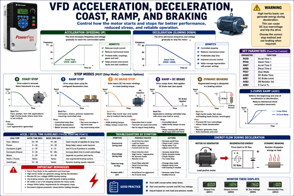
A Variable Frequency Drive does much more than simply turn a motor ON and OFF. One of its biggest advantages is the ability to control how the motor starts and how the motor stops.
Instead of applying full voltage instantly like a traditional across-the-line starter, a VFD can gradually increase motor speed using an acceleration ramp. When stopping, the drive can also control how the motor slows down using deceleration, coast stop, ramp stop, DC braking, or dynamic braking.
Understanding these concepts helps technicians troubleshoot common problems such as:
[ ] Motor takes too long to start
[ ] Drive trips on overcurrent during acceleration
[ ] Drive trips on overvoltage during deceleration
[ ] Load does not stop fast enough
[ ] Motor coasts longer than expected
[ ] Braking resistor overheats
[ ] Mechanical load creates regeneration
[ ] Conveyor, fan, pump, or mixer stops incorrectly
The examples in this post use Allen-Bradley PowerFlex drives as a practical reference, but the concepts apply to most industrial VFDs regardless of manufacturer.
1. What Is Acceleration in a VFD?
Acceleration is the controlled increase of motor speed from a lower frequency to a higher frequency.
Instead of the motor trying to jump instantly to full speed, the VFD gradually increases the output frequency and voltage.
Simple example:
0 Hz → 10 Hz → 20 Hz → 30 Hz → 40 Hz → 50 Hz → 60 HzThe motor follows that ramp and accelerates smoothly.
On a PowerFlex-style drive, common acceleration parameters include:
P039 [Accel Time 1]
A067 [Accel Time 2]
The PowerFlex 4 parameter list includes P039 Accel Time 1, P040 Decel Time 1, A067 Accel Time 2, and A068 Decel Time 2, showing that the drive can use primary and secondary ramp times.
Simple Explanation
Acceleration Time = How long the drive takes to speed up the motor.Example:
Accel Time = 10 secondsThat means the drive ramps the motor from 0 Hz to the commanded speed over the configured time.
2. Why Acceleration Time Matters
Acceleration time affects both the electrical and mechanical behavior of the system.
A good acceleration time can reduce:
[ ] Inrush current
[ ] Mechanical shock
[ ] Belt stress
[ ] Coupling stress
[ ] Gearbox stress
[ ] Product movement issues
[ ] Overcurrent trips
[ ] Motor stalled faults
If acceleration time is too short, the motor may demand more current than the drive can provide.
The PowerFlex troubleshooting table lists F6 Motor Stalled as a condition where the drive is unable to accelerate the motor, and recommends increasing the acceleration time or reducing the load so drive output current does not exceed the current limit.
Field Example: Conveyor Starts Too Hard
Problem:
A conveyor starts too aggressively and product shifts or falls.Possible correction:
Increase Accel Time.Instead of reaching full speed in 1 second, the conveyor may ramp up over 5 or 10 seconds.
3. What Is Deceleration in a VFD?
Deceleration is the controlled decrease of motor speed from a higher frequency to a lower frequency or to zero.
Simple example:
60 Hz → 50 Hz → 40 Hz → 30 Hz → 20 Hz → 10 Hz → 0 HzOn a PowerFlex-style drive, common deceleration parameters include:
P040 [Decel Time 1]
A068 [Decel Time 2]
The PowerFlex parameter description shows acceleration and deceleration as speed ramps over time, using parameters such as P039/A067 Accel Time and P040/A068 Decel Time.
Simple Explanation
Deceleration Time = How long the drive takes to slow down the motor.Example:
Decel Time = 15 secondsThat means the drive attempts to reduce motor speed to zero over 15 seconds, depending on stop mode and load behavior.
4. Why Deceleration Time Matters
Deceleration time is critical because the load may push energy back into the VFD while slowing down.
This is called regeneration.
The glossary defines regeneration as the characteristic of an AC motor acting as a generator when the shaft speed is greater than the synchronous speed for the applied frequency.
This can happen when:
[ ] A large fan is spinning down
[ ] A conveyor has high inertia
[ ] A centrifuge is stopping
[ ] A mixer has a heavy load
[ ] A load is overhauling the motor
[ ] A downhill conveyor pushes the motor
When regeneration occurs, energy flows back into the drive and raises the DC bus voltage.
5. Deceleration and Overvoltage Faults
One of the most common VFD stopping problems is:
Drive trips on OverVoltage during deceleration.This often happens because the drive is trying to stop the load too quickly.
The PowerFlex troubleshooting table states that F5 OverVoltage occurs when the DC bus voltage exceeds the maximum value. It also notes that bus overvoltage can be caused by motor regeneration and recommends extending the deceleration time or installing a dynamic brake option.
Field Example: Fan Trips on Overvoltage When Stopping
Problem:
A large fan runs normally, but when commanded to stop, the VFD trips on OverVoltage.Possible causes:
[ ] Decel time too short
[ ] Fan inertia pushing energy back
[ ] No braking resistor installed
[ ] Dynamic brake not enabled
[ ] High incoming line voltage
[ ] Stop mode not suitable for the load
Possible corrective actions:
[ ] Increase Decel Time
[ ] Use Coast Stop if process allows
[ ] Install or verify dynamic braking
[ ] Check braking resistor
[ ] Check DC bus voltage
[ ] Verify stop mode
6. What Is Coast Stop?
Coast stop means the drive removes output power and allows the motor/load to coast naturally to a stop.
Simple explanation:
Drive output OFF → Motor freewheels → Load stops by friction/inertiaCoast stop is common for:
[ ] Fans
[ ] Pumps
[ ] Some blowers
[ ] Low-risk applications where exact stop time is not critical
[ ] Loads where ramping down causes overvoltage
In a PowerFlex 400-style parameter list, P037 Stop Mode includes options such as Ramp, Coast, DC Brake, and DC Brake with Shutoff.
Advantages of Coast Stop
[ ] Simple
[ ] Reduces regeneration into the DC bus
[ ] Useful for high-inertia loads
[ ] May reduce overvoltage trips
Disadvantages of Coast Stop
[ ] Stop time is not controlled
[ ] Load may take too long to stop
[ ] Not good for positioning
[ ] May not meet process or safety expectations
7. What Is Ramp Stop?
Ramp stop means the drive actively reduces motor frequency according to the deceleration time.
Simple explanation:
Drive controls the slowdown using Decel Time.Example:
Decel Time = 10 seconds
Stop Command → Drive ramps from 60 Hz to 0 Hz in 10 seconds
Ramp stop is useful when the process needs a controlled stop.
Applications:
[ ] Conveyors
[ ] Mixers
[ ] Feeders
[ ] Packaging equipment
[ ] Process machines
[ ] Applications where smooth stop matters
Advantages of Ramp Stop
[ ] Controlled stopping
[ ] Smooth process behavior
[ ] Less mechanical shock
[ ] Predictable stop time
Disadvantages of Ramp Stop
[ ] May cause overvoltage on high-inertia loads
[ ] May require braking resistor
[ ] Decel time must be tuned properly
[ ] Not always suitable for emergency stopping
8. Coast Stop vs Ramp Stop
| Feature | Coast Stop | Ramp Stop |
|---|---|---|
| Drive output | Removed quickly | Controlled during decel |
| Stop time | Depends on load inertia | Based on decel setting |
| Control | Low | High |
| Regeneration risk | Lower | Higher |
| Common use | Fans, high inertia loads | Conveyors, mixers, controlled processes |
| Main concern | Load may take too long to stop | Overvoltage if decel too fast |
Simple Technician Explanation
Coast Stop = Let it spin down naturally.
Ramp Stop = Drive controls the slowdown.
9. What Is DC Braking?
DC braking is a method where the drive injects DC into the motor windings to create braking torque.
This does not control speed the same way as a ramp. Instead, DC injection helps hold or slow the motor near low speed or stop, depending on the drive and settings.
PowerFlex-style parameters may include:
A080 [DC Brake Time]
A081 [DC Brake Level]
The PowerFlex 4 parameter list includes DC Brake Time A080, DC Brake Level A081, and DB Resistor Sel A082 in the Advanced Program Group.
Where DC Braking May Be Used
[ ] Stop assist near zero speed
[ ] Preventing coast at the end of stop
[ ] Low-inertia applications
[ ] Some fans or light machinery
[ ] Holding momentarily after stop, if supported
DC Braking Warning
Too much DC braking can cause:
[ ] Motor heating
[ ] Overcurrent faults
[ ] Drive stress
[ ] Mechanical stress
[ ] Nuisance trips
The PowerFlex troubleshooting table notes that hardware overcurrent can be related to excess load, improper boost setting, or DC brake volts set too high.
10. What Is Dynamic Braking?
Dynamic braking is used when the motor/load regenerates energy back into the drive during deceleration.
Instead of allowing the DC bus voltage to rise too high, the braking circuit sends that energy to a braking resistor, where it is dissipated as heat.
Simple flow:
Motor regenerates energy
        ↓
Energy flows back to DC bus
        ↓
Dynamic brake circuit turns on
        ↓
Braking resistor dissipates energy as heat
During stopping, frequency and voltage are ramped down at a controlled rate, and that additional braking torque can be applied by adding a braking circuit to dissipate braking energy or return it to the power source.
Where Dynamic Braking Is Common
[ ] High-inertia conveyors
[ ] Centrifuges
[ ] Hoists
[ ] Unwinders
[ ] Large fans requiring fast stop
[ ] Downhill conveyors
[ ] Applications with frequent deceleration
11. Dynamic Braking Resistor
A dynamic braking resistor converts regenerated energy into heat.
Important field checks:
[ ] Is the braking resistor installed?
[ ] Is it wired correctly?
[ ] Is it sized correctly?
[ ] Is it overheating?
[ ] Is the duty cycle correct?
[ ] Is the drive parameter enabled?
[ ] Is the resistor open or damaged?
On a PowerFlex-style drive, the parameter may be:
A082 [DB Resistor Sel]The PowerFlex 4 manual describes A082 [DB Resistor Sel] as the parameter that enables or disables external dynamic braking and includes duty-cycle-related settings.
12. S-Curve Acceleration and Deceleration
Some drives include S-curve ramping.
Instead of a straight linear ramp, the VFD softens the beginning and end of acceleration or deceleration.
This helps reduce mechanical shock.
Applications:
[ ] Conveyors with unstable product
[ ] Packaging lines
[ ] Bottling lines
[ ] Delicate material handling
[ ] Systems with belts or chains
The PowerFlex 4 manual describes A083 [S Curve %] as a parameter that applies a percentage of acceleration or deceleration time to the ramp as an S-curve, adding time at the beginning and end of the ramp.
Simple Explanation
Linear Ramp = speed changes at a constant rate.
S-Curve Ramp = speed changes gently at the beginning and end.
This can help prevent jerking, product tipping, or mechanical shock.
13. Multiple Accel/Decel Times
Many VFDs allow more than one acceleration and deceleration profile.
Example:
Accel Time 1 / Decel Time 1 = Normal operation
Accel Time 2 / Decel Time 2 = Alternate process mode
This is useful when a machine has different operating modes.
Examples:
[ ] Normal run
[ ] Jog mode
[ ] Cleaning mode
[ ] Recipe mode
[ ] Heavy load mode
[ ] Empty conveyor mode
[ ] Fast stop mode
PowerFlex 400 specifications state that the drive includes two independently programmable acceleration and deceleration times, programmable from 0 to 600 seconds in 0.1 second increments.
14. Accel/Decel and PLC Control
When a PLC controls a VFD, the PLC may send:
[ ] Run command
[ ] Stop command
[ ] Speed reference
[ ] Preset speed selection
[ ] Accel/decel profile selection
[ ] Fault reset
But the actual ramping is usually performed inside the VFD.
The PLC says:
Run at 45 HzThe VFD decides:
I will ramp to 45 Hz using the configured acceleration time.Good PLC Tag Examples
VFD_Run_Cmd
VFD_Stop_Cmd
VFD_Speed_Ref
VFD_AccelRate2_Enable
VFD_DecelRate2_Enable
VFD_RampStop_Cmd
VFD_CoastStop_Cmd
VFD_Faulted
VFD_OverVoltage
VFD_OutputFreq
VFD_DC_BusVoltage
15. Choosing the Right Stop Method
The best stop method depends on the machine.
| Application | Typical Stop Consideration |
|---|---|
| Fan | Coast may be acceptable; ramp may overvoltage |
| Pump | Ramp stop may reduce water hammer |
| Conveyor | Ramp stop usually preferred |
| Mixer | Depends on product and inertia |
| Hoist | Requires engineered braking/safety design |
| Centrifuge | Dynamic braking may be required |
| Packaging line | S-curve may help prevent product movement |
Technician Note
Never assume one stop mode is best for every application.
Ask:
[ ] Does the process require controlled stopping?
[ ] Is stop time critical?
[ ] Does the load have high inertia?
[ ] Does the motor regenerate during decel?
[ ] Is a braking resistor installed?
[ ] Is the stop related to safety?
[ ] Will coast stop create a hazard?
[ ] Will ramp stop cause overvoltage?
16. Important: Normal Stop vs Emergency Stop
A VFD stop command is not automatically a safety-rated stop.
Normal stop methods include:
[ ] Ramp stop
[ ] Coast stop
[ ] DC brake stop
Emergency stopping must be designed according to the machine risk assessment and applicable safety requirements.
Depending on the equipment, the safety design may include:
[ ] Safety relay
[ ] Safe Torque Off, if supported
[ ] Safety-rated contactors
[ ] Mechanical brake
[ ] Controlled stop category
[ ] Power removal
Do not confuse a VFD stop parameter with a complete machine safety function.
17. Troubleshooting by Symptom
Problem: Drive Trips on Overcurrent During Start
Possible causes:
[ ] Accel time too short
[ ] Load too heavy
[ ] Mechanical jam
[ ] Motor data incorrect
[ ] Current limit too low
[ ] Boost setting incorrect
[ ] Motor wiring problem
Corrective action:
[ ] Increase Accel Time
[ ] Check load mechanically
[ ] Verify motor FLA
[ ] Check current limit
[ ] Check boost settings
[ ] Check motor leads
Problem: Drive Trips on Overvoltage During Stop
Possible causes:
[ ] Decel time too short
[ ] High-inertia load
[ ] Regeneration
[ ] No dynamic brake
[ ] Braking resistor issue
[ ] High incoming line voltage
Corrective action:
[ ] Increase Decel Time
[ ] Try Coast Stop if acceptable
[ ] Verify dynamic braking setup
[ ] Check brake resistor
[ ] Monitor DC bus voltage
[ ] Check incoming voltage
Problem: Motor Takes Too Long to Stop
Possible causes:
[ ] Coast stop selected
[ ] Decel time too long
[ ] Load inertia high
[ ] Braking resistor not installed
[ ] DC braking disabled
[ ] Stop command not reaching drive
Corrective action:
[ ] Verify Stop Mode
[ ] Adjust Decel Time
[ ] Evaluate braking requirement
[ ] Check dynamic brake
[ ] Verify stop input/command
Problem: Product Falls or Shifts During Start/Stop
Possible causes:
[ ] Accel too aggressive
[ ] Decel too aggressive
[ ] No S-curve
[ ] Conveyor speed changes too quickly
Corrective action:
[ ] Increase Accel Time
[ ] Increase Decel Time
[ ] Enable S-Curve if supported
[ ] Tune speed transitions
18. Common Mistakes Technicians Should Avoid
[ ] Setting acceleration too short for a heavy load
[ ] Setting deceleration too short without braking hardware
[ ] Using ramp stop on a high-inertia load without checking DC bus voltage
[ ] Assuming overvoltage always means incoming voltage is too high
[ ] Ignoring regeneration during deceleration
[ ] Enabling DC braking too aggressively
[ ] Installing a braking resistor without enabling/checking the parameter
[ ] Using coast stop where controlled stopping is required
[ ] Confusing normal stop with safety-rated emergency stop
[ ] Changing ramp times without documenting original values
Technician Checklist: Accel, Decel, Coast, Ramp, and Braking
[ ] Identify the load type: fan, pump, conveyor, mixer, hoist, etc.
[ ] Verify Accel Time.
[ ] Verify Decel Time.
[ ] Verify Stop Mode.
[ ] Confirm if Coast Stop or Ramp Stop is expected.
[ ] Check if DC braking is enabled.
[ ] Check if dynamic braking is installed.
[ ] Verify braking resistor wiring and condition.
[ ] Monitor output current during acceleration.
[ ] Monitor DC bus voltage during deceleration.
[ ] Check for overcurrent faults during start.
[ ] Check for overvoltage faults during stop.
[ ] Confirm PLC/HMI stop command behavior.
[ ] Document original parameter values before making changes.
Simple Technician Explanation
A simple way to explain this topic is:
Acceleration controls how smoothly the motor speeds up.
Deceleration controls how smoothly the motor slows down.
Coast stop lets the load stop naturally.
Ramp stop makes the drive control the stop.
Braking helps stop the load faster when inertia or regeneration is involved.
Or even shorter:
Accel = controlled start.
Decel = controlled stop.
Coast = let it spin down.
Ramp = drive controls the speed change.
Braking = manage stopping energy.
Final Thoughts
Acceleration, deceleration, coast, ramp, and braking are not just “comfort settings.” They directly affect machine performance, motor current, mechanical stress, stopping time, DC bus voltage, and fault behavior.
A good technician does not only ask:
Why did the drive fault?A good technician asks:
Did the fault happen during acceleration, running, or deceleration?
Was the load pushing energy back into the drive?
Is the ramp time realistic for the machine?
Is braking hardware required?
Is the stop mode correct for the process?
Many VFD faults become easier to understand once you connect the fault to the motion profile:
Start problem → Check Accel Time, load, current limit.
Stop problem → Check Decel Time, stop mode, regeneration, braking.
This mindset turns VFD troubleshooting into a logical process instead of guessing.