22. Industrial Motor Control Best Practices for Automation Technicians (22 of 22)
Practical Guidelines for Safer, Cleaner, and More Reliable Motor Control Systems
Introduction
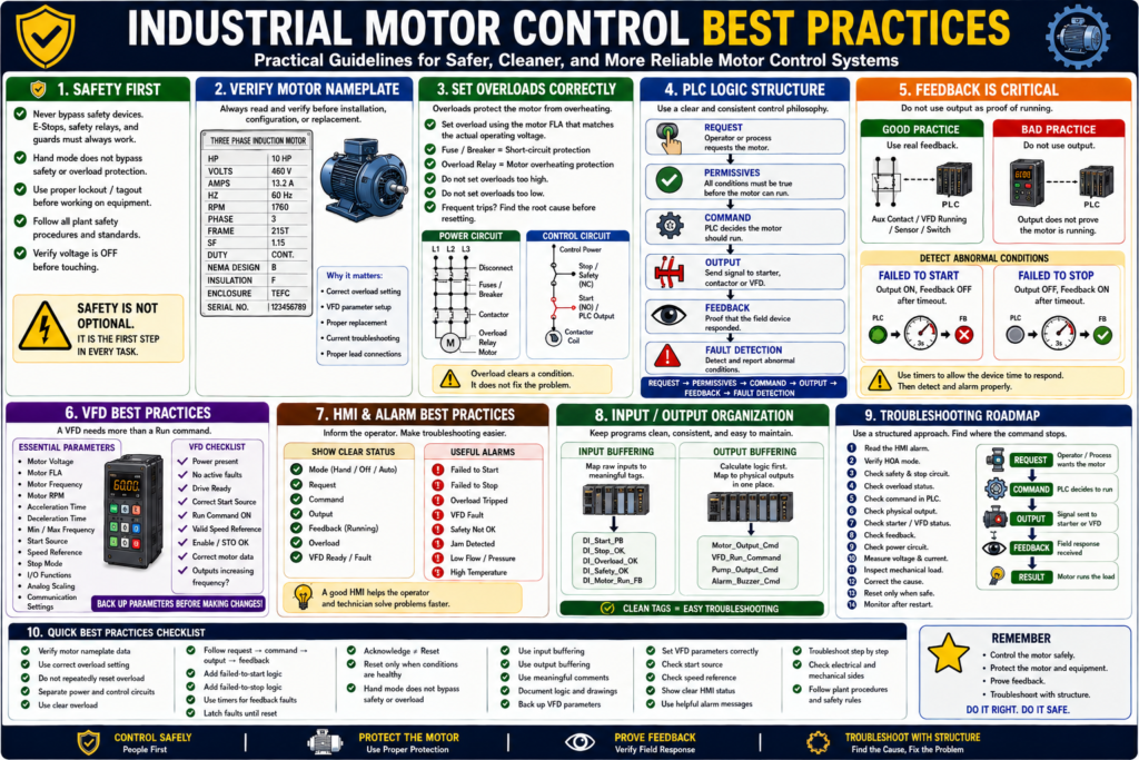
Industrial motor control is more than starting and stopping a motor. A reliable motor control system should be safe, organized, easy to troubleshoot, and clear for operators and technicians.
Throughout this series, we covered important topics such as power circuits, control circuits, contactors, overloads, motor nameplates, three-phase motors, reversing starters, jogging, HOA control, control transformers, pilot lights, feedback, faults, alarms, troubleshooting, VFDs, and PLC motor control.
Now it is time to bring all those ideas together.
A simple way to summarize industrial motor control best practices is:
Control the motor safely, protect the equipment, prove the feedback, and make troubleshooting clear.
This final post is a practical checklist of best practices that automation technicians can apply in real industrial environments.
1. Separate Power Circuit and Control Circuit
One of the first best practices is to understand and separate the power circuit from the control circuit.
The power circuit carries motor current.
L1/L2/L3 → Disconnect → Fuses/Breaker → Contactor → Overload → MotorThe control circuit decides when the motor is allowed to run.
Control Power → Stop/Safety → Start/PLC Output → Coil/VFD CommandThis separation makes troubleshooting easier.
A practical troubleshooting rule:
If the contactor does not pull in, check the control circuit.

If the contactor pulls in but the motor does not run, check the power circuit.
2. Always Verify the Motor Nameplate
Before replacing a motor, setting an overload, configuring a VFD, or troubleshooting high current, always read the motor nameplate.
Important nameplate data includes:
Voltage
Full-load amps
Horsepower
Phase
Frequency
RPM
Service factor
Frame size
Duty
Enclosure
Connection diagram
Never guess motor data.
Practical rule:
The motor nameplate is the motor’s electrical ID card.
This information is critical for:
- Overload settings
- VFD parameters
- Starter sizing
- Replacement selection
- Current troubleshooting
- Motor lead connections
3. Use the Correct Overload Setting
The overload relay protects the motor from excessive current over time.
Set the overload based on the motor nameplate FLA and the actual operating voltage.
Example:
Motor nameplate:
230/460 V
13.2/6.6 A
If the motor is operating at 460 V, use the 6.6 A value.
Do not use the wrong FLA value.
Best practice:
Use the FLA that matches the actual operating voltage.Also remember:
Fuse / Breaker = short-circuit protection
Overload Relay = motor overheating protection
They are not the same device.
4. Do Not Keep Resetting Overloads
An overload trip is a symptom, not the root cause.
Before resetting, check:
Mechanical jam
Pump blockage
Bearing failure
Phase loss
Low voltage
Wrong overload setting
Motor current
Motor nameplate FLA
Frequent starts
Mechanical binding
Practical rule:
Do not reset repeatedly. Find out why the overload tripped.
Repeated resets can damage the motor and hide a real mechanical or electrical problem.
5. Separate Request, Command, Output, and Feedback
One of the strongest PLC motor control best practices is to separate the logic into clear stages:
Request → Permissives → Command → Output → Feedback → Fault DetectionEach stage has a different meaning.
| Stage | Meaning |
|---|---|
| Request | Operator or process asks for the motor |
| Permissives | Conditions required before running |
| Command | PLC decides motor should run |
| Output | Physical signal sent to starter or VFD |
| Feedback | Proof that the field device responded |
| Fault Detection | Detects abnormal conditions |
This structure makes the program easier to read, troubleshoot, and expand.
6. Do Not Use Output as Running Feedback
A PLC output ON does not prove the motor is running.
Bad logic:
Motor_Running = Motor_OutputBetter logic:
Motor_Running = Motor_Run_FeedbackFeedback should come from a real field signal such as:
Contactor auxiliary contact
VFD running status
Motor current switch
Flow switch
Pressure switch
Encoder
Limit switch
Best practice:
Command tells the motor what to do. Feedback confirms what actually happened.
7. Add Failed-to-Start Logic
A failed-to-start fault detects when the motor was commanded but did not prove running.
Example logic:
If Motor_Output = ON
AND Motor_Run_Feedback = OFF
after 3 seconds
THEN Motor_Failed_To_Start = ON
This helps detect:
Bad contactor coil
Tripped overload
No control voltage
Broken wire
VFD fault
Bad auxiliary contact
Bad PLC output
Missing drive enable
Recommended HMI message:
Motor Failed to Start — Command ON, but run feedback was not detected.This is much better than simply showing “Motor Fault.”
8. Add Failed-to-Stop Logic
A failed-to-stop fault detects when the motor output is OFF, but feedback remains ON.
Example logic:
If Motor_Output = OFF
AND Motor_Run_Feedback = ON
after 3 seconds
THEN Motor_Failed_To_Stop = ON
Possible causes:
Welded contactor
VFD still running
Feedback contact stuck
Output bypassed
PLC input stuck ON
Incorrect wiring
This condition can be serious because the system may think the motor is stopped when feedback says it is still active.
Recommended HMI message:
Motor Failed to Stop — Feedback remained ON after command was removed.9. Use Meaningful Faults and Alarms
Do not use vague alarm messages.
Weak message:
Motor FaultBetter message:
Conveyor Motor Failed to StartBest message:
Conveyor Motor Failed to Start — Command ON, but run feedback was not detected within 3 seconds.A good fault or alarm should answer:
What happened?
Which device?
What does it mean?
What should be checked?
Can it be reset?
Separate these clearly:
| Type | Meaning |
|---|---|
| Status | Normal machine condition |
| Alarm | Warning or operator attention |
| Fault | Stops or blocks operation |
| Reset | Clears fault after cause is corrected |
10. Acknowledge Is Not the Same as Reset
This is very important for operators.
Acknowledge means:
The operator has seen the alarm.Reset means:
The cause has been corrected and the fault latch can clear.A reset button should not hide an active problem.
Bad reset logic:
Reset_PB clears all faults immediately.Better reset logic:
Reset_PB clears fault only when the fault condition is no longer active.Example:
If Reset_PB
AND Overload_OK
AND Safety_OK
AND NOT VFD_Faulted
THEN clear Motor_Fault
11. Keep Safety Hardwired Where Required
Safety functions should not depend only on standard PLC logic unless the system is designed with safety-rated hardware.
Examples of safety-related devices:
E-Stops
Safety relays
Guard switches
Light curtains
Safety gates
Safe Torque Off
Emergency stop circuits
Best practice:
A standard PLC output should not be the only thing stopping hazardous motion.
Always follow plant safety standards, approved procedures, and qualified electrical practices.
12. Do Not Let Hand Mode Bypass Safety
HOA control is useful, but Hand mode must be designed carefully.
Hand mode may bypass automatic process logic, but it should not bypass:
E-Stop
Safety relay
Overload protection
Critical interlocks
Drive fault
Safe Torque Off
Required guard conditions
Good logic:
Motor_Output =
    Hand_Request OR Auto_Request
    AND Safety_OK
    AND Overload_OK
    AND No_Faults
Best practice:
Hand mode is manual control, not unsafe control.
Also remember:
HOA Off is not lockout/tagout.13. Use Input Buffering
Input buffering means mapping raw PLC inputs to clear internal tag names.
Instead of using raw addresses everywhere, create readable tags.
Example:
Local:1:I.Data.0 → DI_Start_PB
Local:1:I.Data.1 → DI_Stop_OK
Local:1:I.Data.2 → DI_Overload_OK
Benefits:
- Cleaner logic
- Easier troubleshooting
- Easier hardware changes
- Better documentation
- Easier simulation
- More readable programs
Best practice:
Use clear input tags before using signals in main logic.
14. Use Output Buffering
Output buffering means calculating internal output commands first, then mapping them to physical outputs in one place.
Example:
Motor_Output_Cmd = Motor_Run_Command AND Safety_OK AND Overload_OKThen:
DO_Motor_Starter = Motor_Output_CmdBenefits:
- Prevents duplicate output logic
- Easier to troubleshoot
- Cleaner program structure
- Safer output management
- One place for physical output mapping
Best practice:
Calculate logic first. Map physical outputs last.
15. Use Clear Tag Names
Good tag names make troubleshooting easier.
Weak tag names:
Motor1
Bit_01
RunBit
Fault123
Output_Status
Better tag names:
Conveyor_Run_Command
Conveyor_Output_Cmd
Conveyor_Run_FB
Conveyor_Overload_OK
Conveyor_Failed_To_Start
Conveyor_Failed_To_Stop
A good tag name should describe the signal’s purpose.
Practical rule:
Use intention-based names, not mystery bits.
16. Use Short but Meaningful Comments
Good comments explain the intent of the logic, not just the obvious action.
Weak comment:
Turns on motor.Better comment:
Generate motor run command when start request is active and permissives are healthy.Weak comment:
Timer done bit.Better comment:
Detect failed-to-start condition if feedback is not received within timeout.Best practice:
Comment the purpose of the rung, not only what the instruction does.
17. Protect Direction Logic
For reversing starters, forward and reverse must never energize at the same time.
Use multiple layers of protection:
PLC interlock
Electrical auxiliary contact interlock
Mechanical contactor interlock
Direction change delay
Limit switches where required
Example:
Forward_Output =
    Forward_Command
    AND NOT Reverse_Output
    AND NOT Reverse_Feedback
Reverse_Output =
Reverse_Command
AND NOT Forward_Output
AND NOT Forward_FeedbackBest practice:
Never rely on only one method to prevent forward and reverse conflict.
18. Use Jog Correctly
Jogging should be momentary.
Correct behavior:
Hold Jog → Motor runs
Release Jog → Motor stops
Incorrect behavior:
Press Jog → Motor seals in and keeps runningBest practice:
Jog_Command should energize the output, but it should not latch Run_Command.Example:
Motor_Output =
    (Motor_Run_Command OR Motor_Jog_Command)
    AND Safety_OK
    AND Overload_OK
But:
Motor_Jog_Command must not seal in Motor_Run_Command.19. Configure VFDs with Nameplate Data
A VFD must be configured with correct motor information.
Important VFD parameters:
Motor Voltage
Motor FLA
Motor Frequency
Motor RPM
Motor HP or kW
Acceleration Time
Deceleration Time
Minimum Frequency
Maximum Frequency
Start Source
Speed Reference
Stop Mode
Digital Input Functions
Analog Input Scaling
Communication Settings
Practical rule:
A VFD can only protect and control the motor correctly if the parameters are correct.
Before replacing a VFD, try to get:
Parameter backup
Motor nameplate photo
Fault history
Wiring photos
Communication settings
I/O assignments
Application notes
20. Check Start Source and Speed Reference First
Many VFD problems are caused by incorrect command or reference setup.
A VFD needs:
Power
No active fault
Enable / STO healthy
Correct start source
Run command
Valid speed reference
Correct motor parameters
Common issue:
Run Command = ON
Drive Ready = YES
Drive Fault = NO
Speed Reference = 0.0 Hz
In this case, the drive may be ready, but the motor will not move because the speed reference is zero.
Best practice:
When a VFD does not run, check both start source and speed reference.
21. Show Useful HMI Motor Status
A good motor faceplate should help troubleshooting.
Recommended HMI indicators:
Mode: Hand / Off / Auto
Request: Active / Inactive
Command: ON / OFF
Output: ON / OFF
Feedback: Running / Stopped
Overload: OK / Tripped
VFD: Ready / Faulted
Safety: OK / Not OK
Fault: Active / Clear
Runtime Hours
Start Count
Last Fault
Recommended HMI messages:
Motor Ready
Motor Running
Motor in Hand Mode
Motor in Off Mode
Auto Request Blocked
Motor Failed to Start
Motor Failed to Stop
Motor Overload Tripped
VFD Fault Active
Safety Circuit Not Healthy
Best practice:
The HMI should help the technician find the problem faster.
22. Troubleshoot Step by Step
Do not troubleshoot randomly.
Use a structured path:
1. Read the HMI alarm.
2. Verify HOA mode.
3. Check safety and stop circuit.
4. Check overload status.
5. Check command and output.
6. Check feedback.
7. Verify control voltage.
8. Check contactor or VFD.
9. Check power circuit.
10. Measure voltage and current.
11. Inspect mechanical load.
12. Correct the cause.
13. Reset only when safe.
14. Monitor after restart.
A strong troubleshooting phrase:
Find where the command stops.
Practical Motor Control Checklist
Use this checklist when reviewing a motor control system:
Motor nameplate verified
Overload setting matches motor FLA
Safety circuit is not bypassed
HOA mode is clearly defined
Hand mode does not bypass safety
Request, command, output, and feedback are separated
Running status uses feedback
Failed-to-start logic exists
Failed-to-stop logic exists
Faults latch until reset
Reset only works when conditions are healthy
HMI messages are clear
VFD parameters are backed up
Start source and speed reference are documented
Input buffering is used
Output buffering is used
Tag names are meaningful
Rung comments explain intent
Troubleshooting path is documented
Common Mistakes to Avoid
Mistake 1 — Guessing Instead of Measuring
Always verify voltage, current, feedback, and status.
Mistake 2 — Resetting Faults Without Reading Them
Read the alarm first. Fault information is valuable.
Mistake 3 — Using Output as Feedback
A command does not prove field response.
Mistake 4 — Letting Hand Mode Bypass Protection
Manual does not mean unsafe.
Mistake 5 — No VFD Parameter Backup
A replacement VFD without parameters may not run the machine correctly.
Mistake 6 — Ignoring Mechanical Load
Many electrical symptoms are caused by mechanical problems.
Mistake 7 — Poor HMI Messages
“Motor Fault” is not enough for fast troubleshooting.
Mistake 8 — Duplicate Outputs
Do not control the same physical output from multiple locations.
Industrial Pro Tips
Pro Tip 1 — Build a Standard Motor Template
A standard motor template should include:
Inputs
Mode
Requests
Permissives
Commands
Outputs
Feedback
Faults
Alarms
HMI status
This improves consistency.
Pro Tip 2 — Document VFD Settings
Keep records of:
Motor data
Start source
Speed reference
Ramps
Stop mode
Digital inputs
Analog scaling
Network settings
Fault reset method
This makes replacement and troubleshooting much faster.
Pro Tip 3 — Use Feedback Everywhere It Matters
Use feedback for:
Running status
Failed-to-start detection
Failed-to-stop detection
HMI status
Alarm logic
Diagnostics
Pro Tip 4 — Think Electrical and Mechanical
A motor system is both electrical and mechanical.
Always consider:
Control logic
Power wiring
Protection devices
Feedback
Drive configuration
Mechanical load
Process response
Pro Tip 5 — Keep the Operator Informed
A good control system should tell the operator:
What is happening
Why the motor is blocked
What fault is active
What needs to be checked
Whether reset is allowed
Clear information reduces downtime.
Quick Summary
Separate power and control circuits.

Read the motor nameplate before settings or replacement.

Set overloads using the correct FLA.

Do not repeatedly reset overloads.

Separate request, command, output, and feedback.

Use feedback for running status.

Add failed-to-start and failed-to-stop logic.

Use clear alarms and fault messages.

Acknowledge is not the same as reset.

Hand mode should not bypass safety.

Use input and output buffering.

Use clear tag names and meaningful comments.

Configure VFDs with correct motor data.

Back up VFD parameters.

Troubleshoot step by step.

Find where the command stops.
Final Thoughts
Industrial motor control is a foundation skill for automation technicians. Motors move the real equipment in the plant: conveyors, pumps, fans, mixers, compressors, hoists, doors, and production machinery.
A good motor control system should not only make the motor run. It should make the motor run safely, reliably, and with enough feedback to know what is actually happening.
The strongest motor control philosophy is:
Request → Permissives → Command → Output → Feedback → Fault DetectionThis approach helps operators understand the machine, helps technicians troubleshoot faster, and helps protect equipment from damage.
The goal is not just to restart a motor after a problem. The goal is to understand why the problem happened, correct the root cause, and prevent it from returning.
That is what turns basic motor control into real industrial motor control.