21. Motor Control with PLCs: Requests, Commands, Outputs, Feedback, and Faults (21 of 22)
How PLCs Command, Monitor, and Protect Industrial Motors
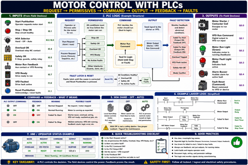
Introduction
In modern industrial automation, many motors are controlled by a PLC, or Programmable Logic Controller. The PLC does not usually power the motor directly. Instead, it makes the control decision and sends an output signal to a motor starter, contactor, interposing relay, soft starter, or VFD.
A simple way to understand it is:
The PLC decides when the motor should run. The starter or VFD actually controls power to the motor.
PLC-based motor control gives us more than simple Start/Stop operation. It allows the system to check safety, permissives, overload status, mode selection, feedback, faults, alarms, timers, sequences, and HMI commands before allowing a motor to run.
A strong PLC motor control structure is:
Request → Permissives → Command → Output → Feedback → Fault DetectionThis structure makes the logic easier to troubleshoot, easier to expand, and more reliable in real industrial equipment.
Why Use a PLC for Motor Control?
Traditional motor control can be done with hardwired pushbuttons, relays, contactors, and overloads. That is still very important to understand.
However, a PLC gives more flexibility.
A PLC can:
- Start and stop motors from logic
- Read HMI commands
- Monitor overload status
- Verify motor feedback
- Detect failed-to-start faults
- Detect failed-to-stop faults
- Control motors in automatic sequences
- Manage Hand-Off-Auto operation
- Interface with VFDs
- Display alarms and status on an HMI
- Track runtime hours and start counts
- Apply interlocks and permissives
- Help technicians troubleshoot faster
In simple terms:
Hardwired control makes the motor run. PLC control makes the motor intelligent.
PLC Motor Control System Overview
A basic PLC motor control system usually includes:
Inputs → PLC Logic → Outputs → Motor Starter / VFD → Motor → FeedbackTypical PLC Inputs
Start_PB
Stop_PB
HOA_Hand
HOA_Auto
Overload_OK
Safety_OK
Motor_Run_Feedback
VFD_Ready
VFD_Running
VFD_Faulted
Reset_PB
Typical PLC Outputs
Motor_Starter_Output
VFD_Run_Command
Motor_Run_Light
Motor_Fault_Light
Motor_Reset_Command
Typical Internal Tags
Motor_Start_Request
Motor_Stop_Request
Motor_Run_Command
Motor_Permissives_OK
Motor_Failed_To_Start
Motor_Failed_To_Stop
Motor_Fault_Active
Motor_Ready
The PLC uses all of this information to decide if the motor is allowed to run.
The Recommended PLC Motor Control Philosophy
A good PLC program should not mix everything into one messy rung.
Instead, separate the logic into sections:
1. Input signals
2. Mode logic
3. Requests
4. Permissives
5. Faults
6. Commands
7. Outputs
8. Feedback monitoring
9. HMI status
This makes the logic easier to read and troubleshoot.
The core philosophy is:
Request → Command → Output → FeedbackLet’s break that down.
1. Request
A request is the operator or process asking for the motor to run.
Examples:
Start pushbutton pressed
HMI Start button pressed
HOA in Hand
Auto sequence requesting motor
Tank level low
Pressure low
Conveyor line ready
Example tags:
Motor_Start_Request
Motor_Auto_Request
Motor_Hand_Request
Pump_Level_Request
Conveyor_Run_Request
Important:
A request is only an intention. It does not mean the PLC should immediately energize the motor.
The PLC must still check permissives, faults, safety, and overload status.
2. Permissives
A permissive is a condition that must be true before the motor is allowed to run.
Common motor permissives include:
Safety_OK
Overload_OK
Stop_Circuit_OK
VFD_Ready
No_Active_Faults
HOA_Not_Off
Guard_Closed
Downstream_Ready
Pressure_OK
Level_OK
No_Jam_Detected
Example:
Motor_Permissives_OK =
    Safety_OK
    AND Overload_OK
    AND Stop_Circuit_OK
    AND No_Active_Faults
Permissives prevent the motor from running under unsafe or abnormal conditions.
3. Command
A command is the PLC’s approved decision to run the motor.
Example:
Motor_Run_Command =
    Motor_Start_Request
    AND Motor_Permissives_OK
The command means:
The PLC has decided the motor should run.However, the command is still not the same as the physical output.
4. Output
The output is the physical signal from the PLC to the field device.
Examples:
PLC output to contactor coil
PLC output to interposing relay
PLC output to VFD run input
Network command to VFD
Example:
Motor_Output =
    Motor_Run_Command
    AND Motor_Permissives_OK
The output energizes the starter coil or sends a run command to the drive.
5. Feedback
Feedback proves that the motor starter, VFD, or process actually responded.
Feedback may come from:
Contactor auxiliary contact
Starter auxiliary contact
VFD running status
VFD at-speed status
Motor current switch
Flow switch
Pressure switch
Encoder
Limit switch
Example:
Motor_Run_Feedback = DI_Motor_Aux_ContactImportant:
Output ON does not prove the motor is running. Feedback proves field response.
Basic PLC Motor Logic Example
Below is a simplified example of motor logic.
Inputs
DI_Start_PB
DI_Stop_OK
DI_Safety_OK
DI_Overload_OK
DI_Motor_Run_FB
DI_Reset_PB
Internal Tags
Motor_Start_Request
Motor_Run_Command
Motor_Output
Motor_Failed_To_Start
Motor_Failed_To_Stop
Motor_Fault_Active
Output
DO_Motor_StarterStart Request Logic
Motor_Start_Request = DI_Start_PBThis means the operator pressed Start.
Fault Active Logic
Motor_Fault_Active =
    Motor_Failed_To_Start
    OR Motor_Failed_To_Stop
    OR NOT DI_Overload_OK
    OR NOT DI_Safety_OK
This combines important fault conditions into one motor fault active bit.
Motor Run Command Logic
Motor_Run_Command =
    Motor_Start_Request
    AND DI_Stop_OK
    AND DI_Safety_OK
    AND DI_Overload_OK
    AND NOT Motor_Fault_Active
This means the PLC only commands the motor if the request is active and the motor is allowed to run.
Final Output Logic
DO_Motor_Starter =
    Motor_Run_Command
    AND DI_Safety_OK
    AND DI_Overload_OK
The final output still includes critical protection.
This is important because the output should not depend only on the command bit.
PLC Seal-In Logic
A motor often needs to stay running after the Start pushbutton is released. In hardwired control, this is done with an auxiliary seal-in contact.
In PLC logic, this can be done using a self-holding rung.
Example:
Motor_Run_Command =
    DI_Stop_OK
    AND DI_Safety_OK
    AND DI_Overload_OK
    AND NOT Motor_Fault_Active
    AND (DI_Start_PB OR Motor_Run_Command)
This means:
Press Start → Motor_Run_Command turns ON
Motor_Run_Command holds itself ON
Press Stop or lose permissive → Motor_Run_Command turns OFF
This is the PLC version of a seal-in circuit.
Better PLC Structure: Separate Request and Command
For industrial-style logic, it is better to separate the Start request from the Run command.
Instead of writing everything in one rung, use clear stages.
Start Request
Motor_Start_Request = DI_Start_PB OR HMI_Start_PBStop Request
Motor_Stop_Request = NOT DI_Stop_OK OR HMI_Stop_PBPermissives
Motor_Permissives_OK =
    DI_Safety_OK
    AND DI_Overload_OK
    AND NOT Motor_Fault_Active
Run Command
Motor_Run_Command =
    Motor_Permissives_OK
    AND NOT Motor_Stop_Request
    AND (Motor_Start_Request OR Motor_Run_Command)
This is cleaner, easier to troubleshoot, and easier to expand.
HOA Control with PLCs
Many motors use Hand-Off-Auto control.
HOA Inputs
DI_HOA_Hand
DI_HOA_Auto
Mode Decode
Hand_Mode = DI_HOA_Hand
Auto_Mode = DI_HOA_Auto
Off_Mode = NOT DI_HOA_Hand AND NOT DI_HOA_Auto
Mode_Conflict = DI_HOA_Hand AND DI_HOA_Auto
Hand Request
Hand_Request =
    Hand_Mode
    AND Local_Start_PB
Auto Request
Auto_Request =
    Auto_Mode
    AND Process_Start_Request
Final Run Request
Motor_Start_Request =
    Hand_Request
    OR Auto_Request
Important:
HOA selects the control source. Safety and protection still decide if the motor is allowed to run.
PLC Motor Control with VFDs
When the motor is controlled by a VFD, the PLC may send:
VFD_Run_Command
VFD_Speed_Reference
VFD_Reset_Command
And the PLC may receive:
VFD_Ready
VFD_Running
VFD_At_Speed
VFD_Faulted
VFD_Output_Frequency
VFD_Output_Current
A basic VFD motor command might look like:
VFD_Run_Command =
    Motor_Run_Command
    AND VFD_Ready
    AND NOT VFD_Faulted
Speed reference may come from:
HMI speed setpoint
PID output
PLC analog output
Network command
Preset speed logic
Example:
VFD_Speed_Reference = HMI_Speed_SetpointImportant:
A VFD needs more than a Run command. It also needs to be ready, not faulted, enabled, and have a valid speed reference.
Command vs Feedback in PLC Motor Control
This is one of the most useful diagnostic concepts.
| Output / Command | Feedback | Meaning |
|---|---|---|
| OFF | OFF | Normal stopped |
| ON | ON | Normal running |
| ON | OFF | Failed to start |
| OFF | ON | Failed to stop or stuck feedback |
Failed to Start Logic
If Motor_Output is ON
AND Motor_Run_Feedback is OFF
after 3 seconds
THEN Motor_Failed_To_Start = ON
Failed to Stop Logic
If Motor_Output is OFF
AND Motor_Run_Feedback is ON
after 3 seconds
THEN Motor_Failed_To_Stop = ON
These two faults make troubleshooting much easier.
Feedback Timer Logic
Feedback should usually be checked with a timer.
Do not create a fault instantly. Give the motor starter or VFD time to respond.
Example:
Motor_Output ON
    ↓
Start feedback timer
    ↓
If feedback does not turn ON before timer done
    ↓
Latch Failed_To_Start fault
Typical delay examples:
| Motor Type | Possible Feedback Delay |
|---|---|
| Small contactor starter | 1–3 seconds |
| Large motor starter | 2–5 seconds |
| VFD motor | 3–10 seconds |
| Pump flow proof | Application dependent |
| Conveyor motion proof | Application dependent |
Use a delay that matches the machine.
Fault Latching and Reset
Real motor faults should usually latch.
Examples:
Motor_Overload_Fault
Motor_Failed_To_Start
Motor_Failed_To_Stop
VFD_Fault
Feedback_Mismatch_Fault
A latched fault remains active until:
The cause is corrected
AND the operator presses Reset
AND reset conditions are valid
Example reset logic:
If Reset_PB
AND DI_Overload_OK
AND DI_Safety_OK
AND NOT VFD_Faulted
THEN clear Motor_Faults
Important:
Reset should not hide an active problem. Reset should only clear the fault after the condition is healthy.
Motor Output Buffering
A professional PLC program often uses output buffering.
This means the logic calculates internal command bits first, then maps them to physical outputs in one place.
Example internal bit:
Motor_Output_CmdPhysical output mapping:
Local:2:O.Data.0 = Motor_Output_CmdOr in tag-based PLC logic:
DO_Motor_Starter = Motor_Output_CmdWhy output buffering helps:
- Easier troubleshooting
- Easier simulation
- Cleaner logic
- Safer output control
- One place to find physical output mapping
- Prevents duplicate output logic
Practical rule:
Calculate logic first. Map physical outputs last.
Input Buffering
Input buffering means raw inputs are mapped to internal tags.
Example raw inputs:
Local:1:I.Data.0
Local:1:I.Data.1
Local:1:I.Data.2
Buffered tags:
DI_Start_PB
DI_Stop_OK
DI_Overload_OK
Why input buffering helps:
- Clear tag names
- Easier troubleshooting
- Easier simulation
- Easier hardware changes
- Better documentation
- Cleaner main logic
Example:
DI_Start_PB = Local:1:I.Data.0
DI_Stop_OK = Local:1:I.Data.1
DI_Overload_OK = Local:1:I.Data.2
Then the motor logic uses the clean tags, not raw addresses.
Motor Faceplate / HMI Status
A good PLC motor control strategy should provide useful HMI data.
Recommended HMI indicators:
Mode: Hand / Off / Auto
Request: Active / Inactive
Command: ON / OFF
Output: ON / OFF
Feedback: Running / Stopped
Overload: OK / Tripped
VFD: Ready / Faulted
Fault: Active / Clear
Ready: Yes / No
Runtime Hours
Start Count
Last Fault
Good HMI messages:
Motor Ready
Motor Running
Motor in Hand Mode
Motor in Off Mode
Auto Request Blocked
Motor Failed to Start
Motor Failed to Stop
Motor Overload Tripped
VFD Fault Active
Safety Circuit Not Healthy
A good HMI should help the operator and technician understand what is happening.
Example Motor Logic Structure
Here is a practical structure for one motor.
Section 1 — Input Buffer
DI_Start_PB
DI_Stop_OK
DI_Safety_OK
DI_Overload_OK
DI_Motor_Run_FB
DI_HOA_Hand
DI_HOA_Auto
Section 2 — Mode Logic
Hand_Mode
Auto_Mode
Off_Mode
Mode_Conflict
Section 3 — Requests
Hand_Request
Auto_Request
Motor_Start_Request
Motor_Stop_Request
Section 4 — Permissives
Motor_Permissives_OK
Motor_Ready
Section 5 — Fault Detection
Motor_Failed_To_Start
Motor_Failed_To_Stop
Motor_Overload_Fault
Motor_Mode_Conflict_Fault
Section 6 — Command Logic
Motor_Run_CommandSection 7 — Output Logic
Motor_Output_CmdSection 8 — Output Buffer
DO_Motor_Starter = Motor_Output_CmdSection 9 — HMI Status
Motor_Status
Motor_Alarm_Text
Motor_Fault_Text
This structure is very clean and easy to troubleshoot.
Common PLC Motor Control Mistakes
Mistake 1 — Using Output as Feedback
Bad:
Motor_Running = Motor_OutputBetter:
Motor_Running = Motor_Run_FeedbackMistake 2 — No Failed-to-Start Fault
If the output turns ON and feedback never appears, the system should detect it.
Mistake 3 — No Failed-to-Stop Fault
If the output turns OFF and feedback stays ON, the system should detect it.
Mistake 4 — Hand Mode Bypasses Safety
Hand mode should not bypass E-Stops, overloads, or critical safety devices.
Mistake 5 — Duplicate Outputs
Do not energize the same physical output from multiple routines.
Use one output buffer location.
Mistake 6 — Poor Tag Names
Avoid vague names:
Motor_Bit
Run1
Output_Status
Fault123
Use meaningful names:
Conveyor_Run_Command
Conveyor_Run_FB
Conveyor_Overload_OK
Conveyor_Failed_To_Start
Troubleshooting PLC Motor Logic
When troubleshooting a PLC-controlled motor, follow this order:
1. Is the Start request active?
2. Is the HOA mode correct?
3. Are permissives satisfied?
4. Is there an active fault?
5. Is the Run command ON?
6. Is the physical output ON?
7. Did the starter or VFD respond?
8. Is feedback ON?
9. Is the mechanical process responding?
10. What does the HMI alarm say?
This follows the same professional troubleshooting path:
Request → Command → Output → Field Device → Feedback → ProcessPractical Example: Conveyor Motor
A conveyor motor is controlled by a PLC.
Inputs
DI_Start_PB
DI_Stop_OK
DI_EStop_OK
DI_Overload_OK
DI_Conveyor_Run_FB
DI_Jam_Clear
Permissives
Conveyor_Permissives_OK =
    DI_EStop_OK
    AND DI_Overload_OK
    AND DI_Jam_Clear
Run Command
Conveyor_Run_Command =
    Conveyor_Permissives_OK
    AND DI_Stop_OK
    AND (DI_Start_PB OR Conveyor_Run_Command)
Output
Conveyor_Output =
    Conveyor_Run_Command
    AND Conveyor_Permissives_OK
Feedback Fault
If Conveyor_Output = ON
AND DI_Conveyor_Run_FB = OFF
after 3 seconds
THEN Conveyor_Failed_To_Start = ON
HMI Message
Conveyor Failed to Start — Command ON, but Run Feedback was not detected.This is clear, practical, and useful.
Practical Example: Pump with VFD
A pump is controlled by a PLC and VFD.
Inputs from VFD
VFD_Ready
VFD_Running
VFD_Faulted
PLC Commands
Pump_Run_Command
Pump_Speed_Reference
Auto Request
Pump_Auto_Request = Tank_Level_LowPermissives
Pump_Permissives_OK =
    VFD_Ready
    AND NOT VFD_Faulted
    AND Safety_OK
    AND Overload_OK
Run Command
Pump_Run_Command =
    Auto_Mode
    AND Pump_Auto_Request
    AND Pump_Permissives_OK
Feedback Check
If Pump_Run_Command = ON
AND VFD_Running = OFF
after 5 seconds
THEN Pump_Failed_To_Start = ON
Process Feedback
If VFD_Running = ON
AND Flow_Proven = OFF
after 10 seconds
THEN Pump_No_Flow_Fault = ON
This is more complete because it checks both drive feedback and process feedback.
Industrial Pro Tips
Pro Tip 1 — Use a Standard Motor Template
Build one clean motor template and reuse the same structure.
Include:
Requests
Permissives
Command
Output
Feedback
Faults
HMI status
Pro Tip 2 — Separate Logic by Purpose
Do not put everything in one rung.
Use organized sections or routines.
Pro Tip 3 — Use Feedback for Running Status
Running status should be based on real feedback, not just output.
Pro Tip 4 — Use Fault Timers
Give the motor time to respond before creating a failed-to-start fault.
Pro Tip 5 — Make HMI Messages Useful
A motor faceplate should help technicians troubleshoot faster.
Quick Summary
PLC motor control uses inputs, logic, outputs, and feedback.

Request = operator or process asks for motor.

Permissives = conditions required before motor can run.

Command = PLC decision to run motor.

Output = physical signal to starter or VFD.

Feedback = proof that the field device responded.

Failed to start = output ON, feedback OFF after timeout.

Failed to stop = output OFF, feedback ON after timeout.

Input buffering makes raw inputs easier to use.

Output buffering keeps physical outputs organized.

A good motor template improves troubleshooting and consistency.
Final Thoughts
Motor control with PLCs is where classic electrical motor control becomes modern industrial automation.
The PLC does not replace the need for proper wiring, overload protection, contactors, VFDs, safety circuits, and mechanical troubleshooting. Instead, the PLC organizes the control decision, checks permissives, commands outputs, monitors feedback, and provides diagnostics to the HMI.
A strong PLC motor control strategy separates:
Request → Permissives → Command → Output → Feedback → Fault DetectionThis structure helps operators understand the motor status, helps technicians troubleshoot faster, and helps the machine run more safely and reliably.
For automation technicians, this is one of the most important control philosophies to learn. Once you understand this structure, you can apply it to conveyors, pumps, fans, mixers, doors, hoists, VFDs, and many other industrial systems.