18. Motor Troubleshooting Guide for Automation Technicians (18 of 22)
A Step-by-Step Guide for Automation Technicians
Introduction
Motor troubleshooting is one of the most important skills for automation technicians, electricians, and maintenance teams. In a real industrial environment, a motor problem can stop a conveyor, pump, fan, mixer, compressor, or entire production line.
When a motor does not start, trips overload, runs in the wrong direction, fails to stop, or shows a fault on the HMI, the technician must troubleshoot in a structured way.
A simple rule is:
Do not guess. Follow the signal from request to motor response.
Many motor problems are not actually caused by the motor itself. The issue may be in the control circuit, power circuit, overload relay, contactor, VFD, PLC output, feedback wiring, safety circuit, or mechanical load.
A strong troubleshooting mindset is:
Request → Command → Output → Field Device → Feedback → Mechanical ResponseSafety First
Before troubleshooting any motor control circuit, always follow site safety procedures.
Motor circuits can involve:
- High voltage
- Arc flash hazards
- Stored electrical energy
- Stored mechanical energy
- Rotating shafts
- Moving conveyors
- Pinch points
- Hydraulic or pneumatic motion
- VFD DC bus voltage
- Unexpected startup
Important:
A stopped motor is not automatically safe.
Always follow proper lockout/tagout procedures when required. The motor control textbook emphasizes electrical safety, lockout/tagout, grounding, bonding, and safe work practices as essential parts of motor control work.
The Big Troubleshooting Question
When a motor does not behave correctly, ask:
Where did the command stop?The problem may be in one of these areas:
| Area | What It Means |
|---|---|
| Operator request | Start PB, HMI command, HOA switch, Auto request |
| PLC logic | Permissives, interlocks, mode, faults |
| Control output | PLC output, relay, VFD run command, starter coil |
| Control circuit | Stop circuit, overload contact, safety contact, coil voltage |
| Power circuit | Fuses, breaker, contactor main contacts, motor leads |
| Feedback | Aux contact, VFD running, current switch, process sensor |
| Mechanical load | Jam, bearing, pump blockage, gearbox, conveyor drag |
Good troubleshooting separates the system into sections instead of randomly checking parts.
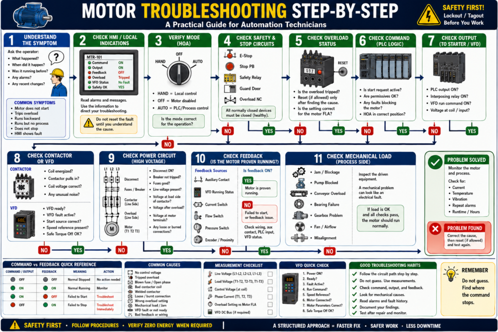
Step 1 — Understand the Symptom
Before opening the panel, understand what the system is doing.
Ask the operator:
What happened?
When did it happen?
Was the motor running before?
Did it trip during startup or while running?
Is there an HMI alarm?
Was anything recently changed?
Did maintenance replace a motor, VFD, fuse, sensor, or contactor?
Common symptoms include:
| Symptom | Possible Direction |
|---|---|
| Motor does not start | Control circuit, output, starter, overload, VFD |
| Motor starts then trips | Overload, mechanical load, low voltage, phase loss |
| Motor runs backward | Phase sequence issue |
| Motor hums but does not turn | Phase loss, locked rotor, bad connection |
| Motor runs but no process result | Mechanical coupling, pump/fan/process issue |
| Motor command ON but feedback OFF | Failed to start condition |
| Motor command OFF but feedback ON | Failed to stop, welded contactor, stuck feedback |
| VFD fault active | Drive fault, parameter, wiring, motor/load issue |
Step 2 — Check the HMI or Local Indications
Before using a meter, check what the control system is telling you.
Look for:
Motor command
Motor output
Motor feedback
Overload status
VFD fault
HOA mode
Safety status
Auto request
Permissives
Fault history
A good HMI should not only say:
Motor FaultIt should provide useful information such as:
Motor Failed to Start — Command ON, feedback not detected.
Motor Overload Tripped — Check load before reset.
VFD Fault Active — Read drive fault code.
Safety Circuit Not Healthy — Check E-Stops and guards.
This helps narrow the troubleshooting path.
Step 3 — Verify the Mode: Hand, Off, or Auto
Many motor troubleshooting problems are caused by mode selection.
Check the HOA mode:
HAND
OFF
AUTO
If HOA Is in OFF
The motor should not start from Hand or Auto.
Troubleshooting question:
Is the motor disabled because the selector is in OFF?If HOA Is in HAND
The motor may be under local/manual control.
Troubleshooting question:
Does the local Start/Stop station work?If HOA Is in AUTO
The PLC or process logic controls the motor.
Troubleshooting question:
Is the automatic start request active and are permissives satisfied?Remember:
HOA Off is not lockout/tagout. It is only a control mode.
Step 4 — Check the Command vs Feedback
This is one of the fastest diagnostic methods.
| Command / Output | Feedback | Meaning |
|---|---|---|
| OFF | OFF | Normal stopped condition |
| ON | ON | Normal running condition |
| ON | OFF | Failed to start or feedback missing |
| OFF | ON | Failed to stop, welded contactor, or stuck feedback |
If the PLC output is ON but feedback is OFF, the system wants the motor to run, but the field device did not prove operation.
Possible causes:
No control voltage
Bad PLC output
Bad interposing relay
Tripped overload
Bad contactor coil
Broken wire
VFD not ready
VFD fault
Bad auxiliary contact
Bad feedback input
If output is OFF but feedback is ON, investigate immediately.
Possible causes:
Welded contactor
VFD still running
Feedback contact stuck
Input wiring issue
Bypassed output
PLC input stuck ON
Step 5 — Check Safety and Stop Circuits
Motor control circuits often include normally closed devices in series.
Check:
E-Stop circuit
Stop pushbutton
Safety relay
Guard switches
Light curtain
Overload NC contact
VFD safe torque off, if used
A typical control path may look like:
Control Power → Stop PB → Safety Contact → Overload NC → Starter CoilIf any normally closed device is open, the starter coil will not energize.
Important:
Do not bypass safety devices to make the motor run. Find why the safety circuit is not healthy.
Step 6 — Check the Overload Relay
If the overload is tripped, the motor should not run until the cause is understood.
The overload relay protects the motor from excessive current over time. It is different from a fuse or breaker. The motor control material explains that overload relays allow normal temporary starting current but trip if current remains high enough to damage the motor.
Check:
Is the overload tripped?
Is the overload reset?
Is the overload contact closed?
Is the overload setting correct?
Does it match motor nameplate FLA?
Did the motor trip during start or while running?
Do not keep resetting the overload without finding the cause.
Possible overload causes:
Mechanical jam
Pump blockage
Bearing failure
Conveyor overload
Phase loss
Low voltage
Wrong overload setting
Motor undersized
Locked rotor
Frequent starts
Step 7 — Verify Control Voltage
If the contactor does not pull in, verify control voltage.
Common control voltages:
24 VDC
120 VAC
240 VAC
For a 120 VAC control circuit, check:
Control transformer primary voltage
Primary fuses
Secondary voltage X1-X2
Secondary fuse
Control power switch
Voltage through Stop/Start/OL circuit
Voltage at contactor coil A1/A2
A common troubleshooting rule:
If the contactor does not pull in, troubleshoot the control circuit first.
Possible control circuit issues:
No control voltage
Blown control fuse
Open Stop button
Open safety relay contact
Open overload contact
Bad Start PB
Bad PLC output
Broken wire
Loose terminal
Bad contactor coil
Wrong coil voltage
Step 8 — Check the Contactor or Starter
If the contactor should energize, check both sides.
Control Side
Check:
Voltage at coil A1/A2
Correct coil voltage rating
Coil condition
Loose control wiring
Interposing relay
PLC output status
Power Side
Check:
Incoming voltage at L1/L2/L3
Output voltage at T1/T2/T3
Main contacts condition
Burned or pitted contacts
Loose terminals
Overload power connections
The contactor is the bridge between control and power:
Control circuit energizes coil
Main contacts close
Power circuit feeds motor
If the contactor pulls in but the motor does not run, move to the power circuit.
Step 9 — Check the Power Circuit
If the contactor pulls in but the motor does not run, check the high-current path.
Typical power circuit:
L1/L2/L3 → Disconnect → Fuses/Breaker → Contactor → Overload → T1/T2/T3 → MotorCheck:
Disconnect ON
Breaker not tripped
Fuses good
All three phases present
Voltage at line side of contactor
Voltage at load side of contactor
Voltage leaving overload
Voltage at motor terminals
Loose or burned terminals
For a three-phase motor, measure:
L1-L2
L2-L3
L1-L3
Then, when safe and appropriate, check load side:
T1-T2
T2-T3
T1-T3
Step 10 — Check for Phase Loss
Phase loss is a common cause of motor trouble.
Symptoms:
Motor hums
Motor does not start
Motor runs hot
Motor trips overload
Low torque
Current imbalance
VFD fault
Possible causes:
Blown fuse
Bad contactor pole
Loose wire
Bad breaker pole
Failed disconnect contact
Damaged cable
Utility issue
The motor control textbook notes that overload protection can also guard against loss of a phase on a three-phase system.
Check all three phases. Do not check only one.
Step 11 — Check Motor Current
If the motor runs but trips or overheats, check current.
Use a clamp meter if approved and safe.
Measure:
T1 current
T2 current
T3 current
Compare to motor nameplate FLA.
| Current Reading | Possible Meaning |
|---|---|
| Below FLA | Motor may be lightly loaded |
| Near FLA | Normal if load is rated |
| Above FLA on all phases | Mechanical overload or low voltage |
| One phase very different | Phase imbalance, bad connection, winding issue |
| No current on one phase | Open phase or bad contact |
The nameplate FLA is the reference point for evaluating motor load.
Step 12 — Check the Mechanical Load
Many electrical motor faults are caused by mechanical problems.
Check:
Conveyor jam
Belt tension
Rollers
Bearings
Pump blockage
Fan obstruction
Gearbox issue
Coupling failure
Product buildup
Shaft binding
Misalignment
Excessive friction
A strong field rule:
Electrical symptoms often have mechanical causes.
If the motor trips overload, do not assume the overload relay is bad. Check the load.
Step 13 — Check Motor Rotation
If the motor was replaced or power wiring was changed, verify rotation.
For a three-phase motor:
Swap any two phases to reverse rotation.Wrong rotation can damage:
Pumps
Fans
Conveyors
Mixers
Screw conveyors
Gearboxes
Always follow site procedures for bump testing and rotation checks.
Step 14 — Troubleshoot VFD-Controlled Motors
If the motor is controlled by a VFD, check both the drive and the motor.
Check:
Is the VFD powered?
Is the VFD ready?
Is there a fault code?
Is the start source correct?
Is the speed reference present?
Is Safe Torque Off healthy?
Is the drive in local or remote mode?
Are motor parameters correct?
Is motor FLA entered correctly?
Is the output frequency increasing?
Is the motor connected correctly?
PowerFlex troubleshooting guidance for a drive that does not start includes checking the power circuit, supply voltage, fuses, disconnects, motor wiring, input signals, start source configuration, and fault status.
Important:
A VFD run command is not enough. The drive must be ready, enabled, not faulted, and have a valid speed reference.
Step 15 — Use Feedback to Confirm Real Operation
Feedback can come from:
Contactor auxiliary contact
VFD running status
Current switch
Flow switch
Pressure switch
Encoder
Proximity sensor
Limit switch
A motor may be electrically running, but the process may not be working.
Example:
Pump motor running feedback = ON
Flow proven = OFF
Possible causes:
Closed valve
Air lock
Broken coupling
Blocked suction
Damaged impeller
Bad flow switch
This is why process feedback is valuable.
Common Motor Troubleshooting Scenarios
Scenario 1 — Motor Does Not Start
Check:
HOA mode
Start request
Safety OK
Overload OK
Control voltage
PLC output
Coil voltage
Contactor movement
Power circuit
Motor feedback
Possible causes:
No command
Safety open
Overload tripped
No control voltage
Bad coil
Bad PLC output
VFD fault
Blown fuse
Mechanical jam
Scenario 2 — Motor Starts but Trips Overload
Check:
Motor current
Mechanical load
Voltage balance
Phase loss
Overload setting
Motor nameplate FLA
Bearing condition
Pump or conveyor condition
Possible causes:
Overloaded equipment
Low voltage
Phase loss
Wrong overload setting
Bearing failure
Locked rotor
Frequent starts
Scenario 3 — Contactor Pulls In but Motor Does Not Run
Check:
Line voltage
Load voltage
Fuses
Main contacts
Overload power section
Motor leads
Phase loss
Motor windings
Mechanical load
Possible causes:
Blown fuse
Bad contactor main contact
Open overload phase
Loose motor lead
Missing phase
Bad motor
Scenario 4 — Motor Runs but PLC Shows Not Running
Check:
Auxiliary contact
Feedback wire
PLC input
Input module
Feedback tag
VFD status mapping
HMI tag
Possible causes:
Bad aux contact
Broken wire
Wrong PLC input
Failed input module
Incorrect logic
Scenario 5 — Motor Will Not Stop
This is serious.
Check:
Stop command
PLC output
Contactor state
Auxiliary feedback
VFD status
Output bypass
Welded contactor
Possible causes:
Welded contacts
VFD still running
PLC output stuck
Incorrect logic
Bypassed wiring
Feedback stuck
Use proper safety procedure immediately.
Practical Troubleshooting Flow
Use this flow when a motor problem happens:
1. Read the HMI alarm.
2. Identify the motor and equipment.
3. Verify HOA mode.
4. Check safety and stop circuit.
5. Check overload status.
6. Check command and output.
7. Check feedback.
8. Verify control voltage.
9. Check contactor or VFD.
10. Check power circuit.
11. Measure voltage and current.
12. Inspect mechanical load.
13. Correct the cause.
14. Reset only when safe.
15. Monitor after restart.
Recommended HMI Diagnostic Display
A good motor faceplate should show:
Mode: Hand / Off / Auto
Request: Active / Inactive
Command: ON / OFF
Output: ON / OFF
Feedback: Running / Stopped
Overload: OK / Tripped
VFD: Ready / Faulted
Safety: OK / Not OK
Fault: Active / Clear
Last Fault
Runtime
Start Count
This helps technicians troubleshoot faster.
Troubleshooting Rule: Separate the Problem
Do not treat a motor fault as one big problem.
Separate it into:
Control problem
Power problem
Protection problem
Feedback problem
Drive problem
Mechanical problem
This approach prevents random part replacement.
Common Mistakes in Motor Troubleshooting
Mistake 1 — Assuming the Motor Is Bad
Many motor problems are caused by overloads, contactors, VFDs, fuses, or mechanical load.
Mistake 2 — Resetting Without Reading the Fault
Read the alarm or fault before clearing it.
Mistake 3 — Checking Only PLC Logic
PLC output ON does not prove the motor is running.
Mistake 4 — Ignoring Mechanical Load
A jammed conveyor can look like an electrical problem.
Mistake 5 — Not Checking All Three Phases
Phase loss can cause overheating, humming, and overload trips.
Mistake 6 — Replacing Parts Without Measurements
Measure voltage, current, and feedback before replacing components.
Industrial Pro Tips
Pro Tip 1 — Follow the Circuit Path
Start at the source and move step by step.
Power source → protection → contactor → overload → motorFor control:
Control power → stop/safety → start/PLC output → coil → feedbackPro Tip 2 — Use Command vs Feedback
Output ON + Feedback OFF = field device did not respond.
Output OFF + Feedback ON = field device or feedback may be stuck.
Pro Tip 3 — Check the Nameplate
Always compare actual current to motor FLA.
Pro Tip 4 — Look for Recent Changes
Many problems appear after:
Motor replacement
VFD replacement
Contactor replacement
Sensor replacement
Wiring change
PLC logic edit
Maintenance work
Pro Tip 5 — Document What You Found
Good troubleshooting includes documenting:
Fault message
Voltage readings
Current readings
Overload status
VFD fault code
Root cause
Corrective action
Quick Summary
Motor troubleshooting should be structured, not random.

Start with the symptom and HMI message.

Verify mode, safety, overload, command, output, and feedback.

If the contactor does not pull in, check the control circuit.

If the contactor pulls in but the motor does not run, check the power circuit.

If the motor runs but feedback is missing, check the feedback circuit.

If the motor trips overload, check current, voltage, phase loss, and mechanical load.

Do not reset faults without understanding the cause.
Final Thoughts
Motor troubleshooting is one of the most valuable skills for an automation technician. A motor problem can come from many places: the HMI, PLC logic, safety circuit, overload relay, contactor, VFD, power wiring, feedback signal, or mechanical load.
The best approach is to troubleshoot step by step.
Do not guess. Do not replace parts randomly. Do not reset faults without reading them.
Follow the path:
Request → Command → Output → Field Device → Feedback → Mechanical ResponseWhen you understand this path, motor troubleshooting becomes more logical, faster, and more professional.
The goal is not only to get the motor running again. The goal is to understand why it stopped, correct the root cause, and prevent the problem from returning.