17. Faults and Alarms in Industrial Motor Control (17 of 22)
Understanding Motor Problems, Operator Messages, and Troubleshooting Logic
Introduction
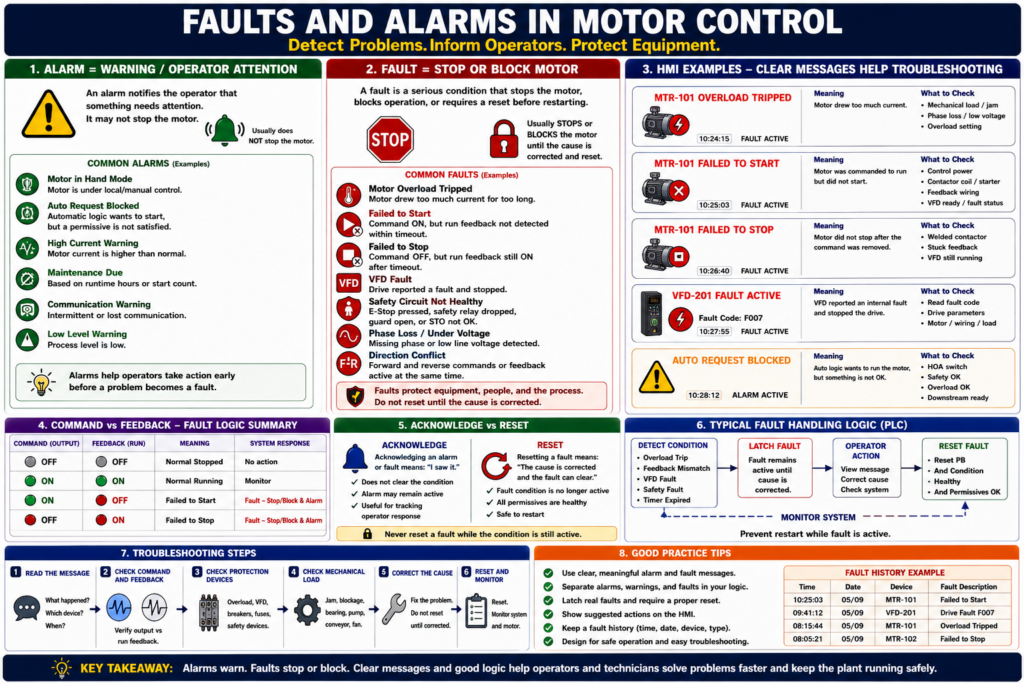
In industrial motor control, faults and alarms help operators and technicians understand when something is wrong, what action is needed, and whether the motor should continue running or stop immediately.
A motor control system should not only start and stop a motor. It should also detect abnormal conditions and communicate them clearly.
A simple way to understand it is:
An alarm warns the operator. A fault usually stops or blocks the machine.
This distinction is important because not every abnormal condition should stop production immediately, but some conditions must stop the motor to protect equipment, people, or the process.
For example, an overload trip is normally treated as a fault because the motor must be stopped and the cause must be corrected before restarting. Overload protection is designed to protect the motor from excessive current and overheating over time.
What Is an Alarm?
An alarm is a condition that warns the operator that something needs attention.
An alarm may or may not stop the motor.
Examples of alarms:
Motor running in Hand mode
Motor current high warning
Filter needs service
VFD warning active
Auto request blocked
Feedback delay warning
Low tank level warning
Communication warning
An alarm is useful when the system wants to say:
Something is abnormal or needs attention, but the equipment may still be allowed to run.What Is a Fault?
A fault is a more serious condition that usually stops the motor, blocks the motor from starting, or requires a reset before operation can continue.
Examples of faults:
Motor overload tripped
Motor failed to start
Motor failed to stop
VFD fault active
E-Stop circuit not healthy
Safety relay dropped
Phase loss
Motor stalled
Drive overcurrent
Contactor welded
Direction conflict
For VFDs, a fault is typically a condition that stops the drive. PowerFlex documentation describes a drive fault as a condition that stops the drive, and the drive provides fault indication such as a flashing fault number and fault indicator.
Alarm vs Fault: Simple Difference
| Condition Type | Meaning | Typical Action |
|---|---|---|
| Alarm | Warns the operator | Investigate, acknowledge, monitor |
| Fault | Stops or blocks operation | Correct cause, reset, restart |
| Warning | Early indication before fault | Monitor or correct soon |
| Status | Normal machine state | No action required |
A good industrial system should not call everything a “fault.” If everything is a fault, operators stop trusting the messages.
Why Faults and Alarms Matter
Faults and alarms improve:
- Operator awareness
- Troubleshooting speed
- Equipment protection
- Motor protection
- Safety response
- Downtime reduction
- Maintenance diagnostics
- HMI clarity
- PLC logic structure
A weak system says:
Motor FaultA better system says:
Conveyor Motor Failed to Start — Command ON, feedback not detected.A professional system gives the technician a clue, not just a red light.
Common Motor Faults
1. Motor Overload Trip
An overload trip happens when the motor draws too much current for too long.
Possible causes:
- Mechanical jam
- Conveyor overload
- Pump blockage
- Low voltage
- Phase loss
- Bearing failure
- Wrong overload setting
- Motor undersized
- Locked rotor
The motor control material explains that overload relays allow harmless temporary overloads, such as starting current, but trip if current remains high enough to damage the motor over time.
Recommended HMI message:
Motor Overload Tripped — Check mechanical load, phase loss, and overload setting before reset.2. Failed to Start
A failed to start fault happens when the PLC commands the motor to run, but feedback does not turn ON within a preset time.
Logic concept:
If Motor_Output = ON
AND Motor_Run_Feedback = OFF
after 3 seconds
THEN Motor_Failed_To_Start = ON
Possible causes:
- Contactor coil not energizing
- No control voltage
- Overload tripped
- Bad auxiliary contact
- Bad PLC output
- Broken wire
- VFD not ready
- VFD faulted
- Start source incorrect
- Motor power missing
PowerFlex troubleshooting guidance for a drive that does not start includes checking the power circuit, supply voltage, fuses, disconnects, motor connections, input signals, start source configuration, and whether the drive is faulted.
Recommended HMI message:
Motor Failed to Start — Command ON, but run feedback was not detected.3. Failed to Stop
A failed to stop fault happens when the PLC removes the motor output, but feedback remains ON after a preset time.
Logic concept:
If Motor_Output = OFF
AND Motor_Run_Feedback = ON
after 3 seconds
THEN Motor_Failed_To_Stop = ON
Possible causes:
- Welded contactor
- Stuck auxiliary contact
- VFD still running
- Output bypassed
- Incorrect wiring
- PLC input stuck ON
- Mechanical system still moving
Recommended HMI message:
Motor Failed to Stop — Feedback remained ON after command was removed.This condition should be treated seriously because the system may believe the motor is stopped when it is still running.
4. VFD Fault
A VFD fault may stop the motor and require correction before restarting.
Common VFD fault categories include:
- Undervoltage
- Overvoltage
- Motor overload
- Hardware overcurrent
- Heatsink overtemperature
- Phase-to-ground fault
- Phase-to-phase short
- Communication loss
- Parameter fault
PowerFlex documentation lists examples such as undervoltage, overvoltage, motor overload, heatsink overtemperature, hardware overcurrent, phase-to-ground faults, phase-to-phase shorts, and communication loss, each with corrective actions.
Recommended HMI message:
VFD Fault Active — Check drive fault code and correct cause before reset.5. Safety Circuit Fault
A safety circuit fault means a safety-related condition is not healthy.
Examples:
E-Stop pressed
Safety relay dropped
Guard door open
Light curtain interrupted
Safety gate unlocked
Safe Torque Off not healthy
Recommended HMI message:
Safety Circuit Not Healthy — Verify E-Stops, guards, and safety relay status.Important:
Do not treat safety faults as normal reset-only alarms. The cause must be verified.
6. Direction Conflict Fault
This applies to reversing starters, doors, hoists, conveyors, and other forward/reverse applications.
Examples:
Forward output and reverse output both ON
Forward feedback and reverse feedback both ON
Reverse command active while forward is running
Direction change requested without stop delay
Recommended HMI message:
Direction Conflict — Forward and Reverse cannot be active at the same time.Forward and reverse contactors should never be energized at the same time because this can create a phase-to-phase short.
7. Feedback Mismatch Fault
A feedback mismatch happens when the expected field signal does not match the command.
Examples:
Command ON, feedback OFF
Command OFF, feedback ON
VFD running but no process flow
Contactor feedback ON but PLC output OFF
Recommended HMI message:
Feedback Mismatch — Verify command, output, auxiliary contact, and field wiring.Common Motor Alarms
1. Motor in Hand Mode
This is usually a status or alarm, not a fault.
Meaning:
Motor is under local/manual control.
Automatic operation may be bypassed or unavailable.
Recommended HMI message:
Motor in Hand Mode — Auto control disabled.2. Auto Request Blocked
This alarm means automatic logic wants to start the motor, but a permissive is missing.
Examples:
Auto request active but HOA is Off
Auto request active but safety not OK
Auto request active but overload not OK
Auto request active but downstream not ready
Recommended HMI message:
Auto Request Blocked — Check HOA mode, permissives, safety, and overload status.3. High Current Warning
This is an early warning before an overload trip.
Possible causes:
- Increasing mechanical load
- Dirty filter
- Pump restriction
- Bearing problem
- Conveyor drag
- Product buildup
Recommended HMI message:
Motor Current High — Inspect load before overload trip occurs.4. Maintenance Due
A maintenance alarm may be based on:
- Runtime hours
- Start count
- VFD run hours
- Motor bearing schedule
- Filter differential pressure
- Lubrication interval
Recommended HMI message:
Motor Maintenance Due — Check runtime-based maintenance schedule.Fault Reset vs Alarm Acknowledge
This is a very important operator concept.
Acknowledge
Acknowledge means:
The operator has seen the alarm.Acknowledge does not necessarily fix the condition.
Example:
Operator acknowledges “Motor Current High.”
The alarm may remain active until current returns to normal.
Reset
Reset means:
The fault latch is cleared after the cause has been corrected.Example:
Overload was tripped.
Cause was corrected.
Overload is healthy.
Operator presses Reset.
Fault clears.
PowerFlex fault clearing follows the same general idea: acknowledge or view the fault, correct the cause, then clear the fault by an approved method such as Stop, cycling power, setting the fault clear parameter, or using a configured digital input.
Why Reset Should Not Hide the Problem
A reset button should not simply erase a real active fault.
Bad logic:
Reset_PB clears all faults immediately.Better logic:
Reset_PB clears fault only when the fault condition is no longer active.Example:
If Reset_PB
AND Overload_OK
AND Safety_OK
AND VFD_Not_Faulted
THEN clear Motor_Fault
This prevents the operator from clearing a fault while the condition still exists.
Recommended Fault Logic Structure
A clean PLC structure separates fault detection, fault latching, and fault reset.
1. Fault Detection
Motor_Failed_To_Start_Condition =
    Motor_Output
    AND NOT Motor_Run_Feedback
    AND Feedback_Timer.DN
2. Fault Latch
If Motor_Failed_To_Start_Condition
THEN Motor_Failed_To_Start_Fault = ON
3. Fault Reset
If Reset_PB
AND NOT Motor_Failed_To_Start_Condition
AND Safety_OK
AND Overload_OK
THEN Motor_Failed_To_Start_Fault = OFF
4. Output Block
Motor_Output =
    Motor_Run_Command
    AND Safety_OK
    AND Overload_OK
    AND NOT Motor_Fault_Active
Recommended Alarm and Fault Table
| Condition | Type | Motor Action | Operator Action |
|---|---|---|---|
| Overload tripped | Fault | Stop/block motor | Inspect load, reset overload, clear fault |
| Failed to start | Fault | Stop/block motor | Check output, coil, VFD, feedback |
| Failed to stop | Fault | Alert/block restart | Check welded contactor or stuck feedback |
| VFD fault | Fault | Drive stops | Read fault code, correct cause |
| E-Stop active | Safety fault/status | Stop/block motor | Verify safety circuit |
| HOA in Hand | Alarm/status | Auto disabled | Verify mode selection |
| Auto request blocked | Alarm | Motor may not start | Check permissives |
| High current warning | Alarm | May continue | Inspect mechanical load |
| Maintenance due | Alarm | Usually continues | Schedule maintenance |
| Communication warning | Alarm/fault depending design | Depends | Check network/device status |
HMI Design Recommendations
A good HMI should show clear fault and alarm information.
Recommended motor faceplate fields:
Mode: Hand / Off / Auto
Command: ON / OFF
Output: ON / OFF
Feedback: Running / Stopped
Overload: OK / Tripped
VFD: Ready / Faulted
Fault: Active / Clear
Alarm: Active / Clear
Reset: Available / Not Available
Recommended alarm details:
Time occurred
Motor tag name
Fault type
Current status
Suggested action
Acknowledge status
Reset status
A strong HMI message should answer:
What happened?
Which device?
What does it mean?
What should the operator check?
Can it be reset?
Examples of Better Alarm Messages
Weak message:
FaultBetter message:
MTR-101 Overload TrippedBest message:
MTR-101 Overload Tripped — Check conveyor jam, motor current, and overload relay before reset.Weak message:
Drive FaultBetter message:
VFD-201 Fault ActiveBest message:
VFD-201 Fault Active — Read drive fault code, correct cause, then clear fault.Weak message:
Not RunningBetter message:
Pump Failed to StartBest message:
P-101 Failed to Start — Command ON, but run feedback was not detected within 3 seconds.Troubleshooting Faults and Alarms
Step 1 — Read the Message
Do not reset first. Read the fault or alarm text.
Ask:
What device?
What condition?
What time?
What action?
Step 2 — Check Command and Feedback
Use the command/feedback table:
| Command | Feedback | Meaning |
|---|---|---|
| OFF | OFF | Normal stopped |
| ON | ON | Normal running |
| ON | OFF | Failed to start |
| OFF | ON | Failed to stop or stuck feedback |
Step 3 — Check Protection Devices
Check:
Overload relay
VFD fault status
Breaker/fuses
Safety relay
Control power
Step 4 — Check Mechanical Load
For motor faults, always consider the mechanical side:
Jam
Bearing
Gearbox
Pump blockage
Conveyor drag
Product buildup
Fan obstruction
Step 5 — Correct the Cause
Do not reset until the cause has been corrected or safely evaluated.
Step 6 — Reset and Monitor
After reset, monitor:
Motor current
Run feedback
VFD status
Temperature
Repeat alarms
Process response
Common Mistakes
Mistake 1 — Resetting Before Reading the Fault
This removes valuable diagnostic information.
Mistake 2 — Calling Every Condition a Fault
Some conditions are alarms or status messages.
Mistake 3 — No Suggested Operator Action
A message should help the operator know what to check.
Mistake 4 — Reset Clears Active Faults
Reset should only clear faults after the condition is healthy.
Mistake 5 — No Fault History
Fault history helps identify repeated problems.
PowerFlex drives maintain recent fault information in fault parameters such as d007 [Fault 1 Code], and fault queues/history are commonly used to retain a limited number of recent faults for troubleshooting.
Industrial Pro Tips
Pro Tip 1 — Use Clear Fault Names
Use:
Motor_Overload_Fault
Motor_Failed_To_Start
Motor_Failed_To_Stop
VFD_Fault
Safety_Not_OK
Avoid vague tags like:
Fault1
Alarm_Bit
Motor_Bad
Pro Tip 2 — Separate Faults, Alarms, and Status
Do not mix everything into one bit.
Faults = stop/block operation
Alarms = warn operator
Status = describe normal state
Pro Tip 3 — Latch Real Faults
Faults like overload trip, failed to start, failed to stop, and VFD fault should usually latch until the issue is corrected and reset.
Pro Tip 4 — Add First-Out Where Possible
For safety chains and complex systems, first-out indication tells which device caused the trip first.
Pro Tip 5 — Make the HMI Useful
The HMI should not only show a red banner. It should help the technician troubleshoot.
Quick Summary
Alarm = warning or abnormal condition that may not stop the motor.

Fault = serious condition that usually stops or blocks the motor.

Acknowledge = operator saw the alarm.

Reset = clear the fault after the cause is corrected.

Overload trip = motor protection fault.

Failed to start = output ON, feedback OFF after timeout.

Failed to stop = output OFF, feedback ON after timeout.

VFD fault = drive stopped or blocked by internal protection.

Good HMI messages should identify the device, condition, and recommended action.
Final Thoughts
Faults and alarms are essential for reliable industrial motor control. They help operators understand what is happening and help technicians find the cause of problems faster.
A good system does not simply say “Motor Fault.” It explains whether the motor overloaded, failed to start, failed to stop, lost feedback, had a VFD fault, or was blocked by a safety or permissive condition.
For automation technicians, the goal is to build and troubleshoot systems that clearly separate:
Status → Alarm → Fault → ResetWhen faults and alarms are designed correctly, the motor control system becomes safer, easier to troubleshoot, and more reliable for production.