11. Reversing Starters Explained for Industrial Motor Control (11 of 22)
How Forward and Reverse Motor Control Works
Introduction
A reversing starter is a motor starter designed to run a three-phase motor in either direction: forward or reverse.
This is common in industrial machines where the motor must move equipment both ways, such as conveyors, hoists, doors, machine tables, actuators, mixers, indexing systems, and material handling equipment.
A simple way to understand it is:
A reversing starter changes motor direction by swapping two of the three motor phases.
The motor control glossary defines a reversing starter as a starter that reverses motor direction by reversing any two leads to the motor.
Why Reversing Starters Are Used
Some applications need motor movement in both directions.
Examples:
| Application | Forward Direction | Reverse Direction |
|---|---|---|
| Conveyor | Move product forward | Back product out |
| Hoist | Lift load | Lower load |
| Door operator | Open door | Close door |
| Machine table | Move right | Move left |
| Screw conveyor | Feed material | Clear jam |
| Mixer/agitator | Normal rotation | Reverse cleanout or process function |
A reversing starter allows the control system to choose which direction the motor should run.
How a Three-Phase Motor Reverses Direction
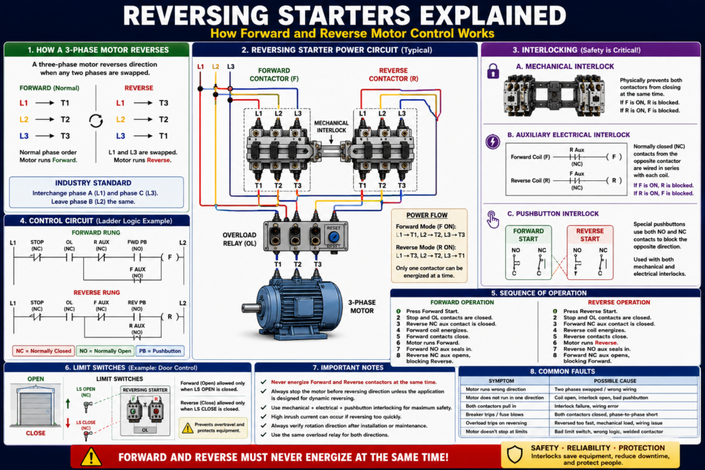
A three-phase motor reverses direction when any two phases are swapped.
Normal forward example:
L1 → T1
L2 → T2
L3 → T3
Reverse example:
L1 → T3
L2 → T2
L3 → T1
In this example, L1 and L3 are swapped.
Interchanging any two leads to a three-phase induction motor causes it to run in the reverse direction, and that the industry standard is commonly to interchange phase A / line 1 and phase C / line 3 while line 2 remains the same.
What Is Inside a Reversing Starter?
A typical three-phase reversing starter includes:
Forward contactor
Reverse contactor
Overload relay
Mechanical interlock
Auxiliary electrical interlocks
Forward/Reverse control circuit
Magnetic full-voltage three-phase reversing starter is constructed using two 3-pole contactors with a single overload relay assembly. One contactor is usually designated forward and the other reverse.
Forward Contactor
The forward contactor connects the phases in the normal order.
Example:
L1 → T1
L2 → T2
L3 → T3
When the forward contactor closes, the motor rotates in the forward direction.
Reverse Contactor
The reverse contactor swaps two phases.
Example:
L1 → T3
L2 → T2
L3 → T1
When the reverse contactor closes, the motor rotates in the opposite direction.
The textbook describes this exact concept: the forward contactor connects L1/L2/L3 to T1/T2/T3, while the reverse contactor swaps the connection so the motor runs in the opposite direction.
Why Interlocking Is Required
This is the most important safety and design concept in reversing starters:
Forward and reverse contactors must never be energized at the same time.
If both contactors close together, the circuit can create a phase-to-phase short circuit.
Interlocking is necessary to prevent both coils from energizing at the same time and creating a phase-to-phase short.
Types of Interlocking
There are three common interlocking methods used in reversing controls:
1. Mechanical interlocking
2. Auxiliary contact electrical interlocking
3. Pushbutton interlocking
Pushbutton, mechanical, and auxiliary contact interlocking as the three methods used on reversing controls.
1. Mechanical Interlocking
A mechanical interlock physically prevents both contactors from closing at the same time.
If the forward contactor is pulled in, the mechanical mechanism blocks the reverse contactor from closing.
If the reverse contactor is pulled in, the mechanism blocks the forward contactor.
Mechanical interlocking is normally factory-installed and uses levers to prevent both contactors from being engaged simultaneously.
Simple concept:
Forward contactor physically ON → Reverse contactor physically blocked
Reverse contactor physically ON → Forward contactor physically blocked
Mechanical interlocking is critical, but it should not be the only method.
2. Auxiliary Contact Electrical Interlocking
Electrical interlocking uses normally closed auxiliary contacts from the opposite contactor.
Most reversing starters use auxiliary contacts operated by the forward and reverse coils to provide electrical interlocking. It describes the logic this way: the normally closed contact controlled by the forward coil is placed in series with the reverse coil, and the normally closed contact controlled by the reverse coil is placed in series with the forward coil.
Forward Rung
Stop_OK AND Forward_PB AND Reverse_Aux_NC AND Overload_OK → Forward_CoilReverse Rung
Stop_OK AND Reverse_PB AND Forward_Aux_NC AND Overload_OK → Reverse_CoilThis means:
If Forward is active, Reverse is blocked.
If Reverse is active, Forward is blocked.
3. Pushbutton Interlocking
Pushbutton interlocking uses special Forward/Reverse pushbuttons with both normally open and normally closed contact blocks.
When the Forward button is pressed, it can open the Reverse circuit.
When the Reverse button is pressed, it can open the Forward circuit.
Pushbutton interlocking should be used together with mechanical and auxiliary electrical interlocking as a supplement, not as a replacement.
Basic Reversing Starter Power Circuit
The power circuit has two possible paths:
Forward Path
L1 → Forward Contactor → T1
L2 → Forward Contactor → T2
L3 → Forward Contactor → T3
Reverse Path
L1 → Reverse Contactor → T3
L2 → Reverse Contactor → T2
L3 → Reverse Contactor → T1
The overload relay is typically shared because the motor needs the same overload protection in either direction.
The textbook states that only one overload relay assembly is required because the motor windings must be protected for the same current level regardless of direction.
Basic Reversing Starter Control Logic
A simple hardwired reversing control circuit has two main coils:
F = Forward contactor coil
R = Reverse contactor coil
Forward Control Logic
Stop_OK
AND Overload_OK
AND Forward_Start
AND Reverse_Not_Active
→ Forward_Coil
Reverse Control Logic
Stop_OK
AND Overload_OK
AND Reverse_Start
AND Forward_Not_Active
→ Reverse_Coil
This prevents both directions from being energized at the same time.
Ladder Style Example
Forward Rung
L1 ----[/ STOP]----[/ OL]----[/ R AUX]----[ FWD PB ]----( F )
                                      |----[ F AUX ]----|
L2
Reverse Rung
L1 ----[/ STOP]----[/ OL]----[/ F AUX]----[ REV PB ]----( R )
                                      |----[ R AUX ]----|
L2
Where:
[/ R AUX] = normally closed reverse auxiliary contact
[/ F AUX] = normally closed forward auxiliary contact
[ F AUX ] = normally open forward seal-in contact
[ R AUX ] = normally open reverse seal-in contact
The normally closed auxiliary contact from the opposite contactor creates the electrical interlock.
Sequence of Operation: Forward
- Operator presses Forward Start.
- Stop circuit and overload contact are healthy.
- Reverse auxiliary NC contact is closed because reverse is not active.
- Forward coil energizes.
- Forward main contacts close.
- Motor runs forward.
- Forward auxiliary NO contact seals in the circuit.
- Forward auxiliary NC contact opens in the reverse circuit, blocking reverse.
Sequence of Operation: Reverse
- Operator presses Reverse Start.
- Stop circuit and overload contact are healthy.
- Forward auxiliary NC contact is closed because forward is not active.
- Reverse coil energizes.
- Reverse main contacts close.
- Motor runs reverse.
- Reverse auxiliary NO contact seals in the circuit.
- Reverse auxiliary NC contact opens in the forward circuit, blocking forward.
Important: Stop Before Reversing
In many applications, the motor should be stopped before reversing direction.
Reversing a motor while it is still spinning can cause:
- High inrush current
- Mechanical shock
- Gearbox stress
- Belt or chain damage
- Coupling stress
- Drive faults
- Product damage
- Contact wear
High inrush currents can damage the motor and controller if the motor is reversed without allowing enough time for speed to decrease.
Practical rule:
Do not command reverse until the forward contactor is dropped out and the motor has safely slowed or stopped, unless the system is specifically designed for that operation.
Reversing Starter with Limit Switches
Reversing starters often use limit switches.
Examples:
| Machine | Forward Limit | Reverse Limit |
|---|---|---|
| Door | Fully open limit | Fully closed limit |
| Hoist | Upper limit | Lower limit |
| Table | Right limit | Left limit |
| Conveyor transfer | Extended limit | Retracted limit |
Limit switches can be used to limit travel of electrically operated doors, conveyors, hoists, machine tool worktables, and similar devices.
Example logic:
Forward allowed = NOT Forward_Limit
Reverse allowed = NOT Reverse_Limit
For a door:
Open_Command allowed only if Door_Not_Fully_Open

Close_Command allowed only if Door_Not_Fully_Closed
Reversing Starter with PLC Logic
In modern systems, the PLC may control the forward and reverse commands.
Recommended PLC tag structure:
DI_Stop_OK
DI_Overload_OK
DI_FWD_PB
DI_REV_PB
DI_FWD_FB
DI_REV_FB
DI_FWD_Limit
DI_REV_Limit

FWD_Request
REV_Request
FWD_Command
REV_Command
FWD_Output
REV_Output
Motor_Fault
PLC Forward Logic
FWD_Command =
    FWD_Request
    AND Stop_OK
    AND Overload_OK
    AND NOT REV_Command
    AND NOT REV_Output
    AND NOT FWD_Limit
    AND No_Faults
PLC Reverse Logic
REV_Command =
    REV_Request
    AND Stop_OK
    AND Overload_OK
    AND NOT FWD_Command
    AND NOT FWD_Output
    AND NOT REV_Limit
    AND No_Faults
Output Logic
FWD_Output = FWD_Command
REV_Output = REV_Command
Important PLC rule:
Never allow both forward and reverse outputs ON at the same time.
Even if the PLC logic blocks it, the physical starter should still have mechanical and electrical interlocking.
Forward/Reverse Feedback
A good control system should verify that the contactor actually responded.
Feedback may come from:
- Forward auxiliary contact
- Reverse auxiliary contact
- VFD running direction status
- Limit switch movement
- Encoder or position feedback
- Motor current status
Example:
If FWD_Output is ON
and FWD_Feedback does not turn ON within 2 seconds,
then latch FWD_Failed_To_Start_Fault.
Reverse example:
If REV_Output is ON
and REV_Feedback does not turn ON within 2 seconds,
then latch REV_Failed_To_Start_Fault.
Also check for impossible feedback:
If FWD_Feedback and REV_Feedback are ON at the same time,
then latch Direction_Feedback_Fault.
HMI Indications for Reversing Starters
A good HMI should clearly show direction and faults.
Recommended status indicators:
Forward Command
Reverse Command
Forward Running Feedback
Reverse Running Feedback
Overload Healthy
Forward Limit
Reverse Limit
Direction Fault
Failed to Start Forward
Failed to Start Reverse
Recommended operator messages:
Motor Running Forward
Motor Running Reverse
Forward Blocked by Reverse Active
Reverse Blocked by Forward Active
Forward Limit Reached
Reverse Limit Reached
Overload Tripped
Direction Feedback Fault
This helps operators understand why a command is not allowed.
Common Reversing Starter Problems
| Symptom | Possible Cause |
|---|---|
| Motor runs wrong direction | Two phases reversed or wrong wiring |
| Forward works, reverse does not | Reverse coil issue, interlock open, bad pushbutton |
| Reverse works, forward does not | Forward coil issue, interlock open, bad pushbutton |
| Contactor chatters | Low control voltage, loose wire, weak coil |
| Motor trips overload when reversing | Reversed too quickly, mechanical load, phase issue |
| Both feedbacks appear ON | Bad auxiliary contacts, wiring issue, PLC input issue |
| Motor does not stop at limit | Bad limit switch, wrong logic, welded contactor |
| Breaker trips on reverse command | Interlock failure, phase-to-phase short, wiring error |
Troubleshooting a Reversing Starter
Step 1 — Verify Safety
Follow plant safety procedures and LOTO requirements. Reversing systems can move equipment unexpectedly in either direction.
Step 2 — Identify Forward and Reverse Contactors
Look for:
F contactor
R contactor
Mechanical interlock
Overload relay
Auxiliary contacts
Step 3 — Check Control Voltage
Verify the control power source and fuses.
Check voltage at:
Forward coil A1/A2
Reverse coil A1/A2
Step 4 — Check Interlocks
Check:
Mechanical interlock movement
Forward NC auxiliary in reverse circuit
Reverse NC auxiliary in forward circuit
Pushbutton interlocking contacts
PLC interlock logic
Step 5 — Check Overload Contact
Verify the overload NC contact is closed.
If overload is tripped, do not simply reset. Investigate the cause.
Step 6 — Check Power Circuit
Verify:
Forward contactor output phases
Reverse contactor output phases
Shared overload connections
Motor leads
Phase swap wiring
Step 7 — Check Feedback
Verify:
Forward auxiliary feedback
Reverse auxiliary feedback
PLC input status
HMI status
Important Safety Warning
A reversing starter has more risk than a simple starter because it can move equipment in two directions.
Before testing:
- Verify machine area is clear.
- Verify direction labels.
- Verify limit switches.
- Verify E-Stops.
- Verify overload protection.
- Verify interlocking.
- Verify mechanical load condition.
Never defeat interlocks to “make it run.” Interlocks exist to prevent dangerous and damaging conditions.
Industrial Pro Tips
Pro Tip 1 — Always Prove the Interlock
Before returning a reversing starter to service, verify that forward and reverse cannot energize together.
Pro Tip 2 — Check Rotation After Replacement
After replacing a motor, contactor, VFD, or starter, verify direction.
Pro Tip 3 — Add a Direction Change Delay
In PLC systems, add a short delay between changing from forward to reverse to allow the motor to stop or slow down.
Example:
Forward OFF → 1 second delay → Reverse allowed
Reverse OFF → 1 second delay → Forward allowed
The correct delay depends on the machine and safety requirements.
Pro Tip 4 — Use Feedback, Not Only Commands
A PLC output does not prove the contactor pulled in.
Use auxiliary feedback.
Pro Tip 5 — Use Limits for Travel Applications
For doors, hoists, and moving tables, direction commands should be blocked by end-of-travel limits.
Quick Summary
Reversing starter = two contactors used to run a motor forward or reverse.

Three-phase motor reversal = swap any two phases.

Forward contactor = normal phase sequence.

Reverse contactor = two phases swapped.

Mechanical interlock = physically prevents both contactors from closing.

Electrical interlock = NC auxiliary contacts block the opposite coil.

Pushbutton interlock = special pushbutton contacts supplement interlocking.

Overload relay = usually shared by both directions.

PLC logic should never allow forward and reverse outputs on at the same time.
Final Thoughts
Reversing starters are a key part of industrial motor control. They allow a three-phase motor to run in two directions by swapping two motor phases.
The most important concept is interlocking. Forward and reverse contactors must never energize at the same time because this can create a phase-to-phase short circuit and damage equipment.
A reliable reversing system uses mechanical interlocking, electrical auxiliary contact interlocking, proper overload protection, clear command logic, feedback monitoring, and safe direction-change behavior.
For automation technicians, reversing starters are a great example of how electrical hardware, ladder logic, PLC programming, safety, and troubleshooting all connect in one system.