4. Start/Stop Seal-In Circuit Explained for Industrial Motor Control (Series Post 4 of 22)
The Foundation of Industrial Motor Control
Introduction
The Start/Stop seal-in circuit is one of the most important circuits in industrial motor control. If you understand this circuit, you are building a strong foundation for reading ladder diagrams, troubleshooting motor starters, and understanding PLC motor control logic.
This circuit is commonly used to start and stop motors using momentary pushbuttons. It allows the motor starter coil to stay energized after the operator releases the Start pushbutton.
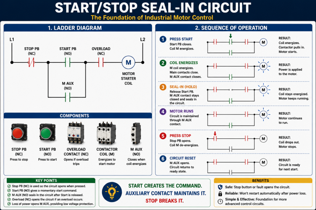
In simple terms:
The Start button energizes the motor starter.
The auxiliary contact keeps it running.
The Stop button breaks the circuit and stops the motor.
This is known as a seal-in circuit, holding circuit, or memory circuit.
The MCTrainer material explains seal-in logic as the condition where pressing the Start button energizes the coil, closes the auxiliary contact, and creates a current path around the Start button until the Stop button opens the circuit.
What Is a Seal-In Circuit?
A seal-in circuit is a control circuit that uses an auxiliary contact to maintain power to a relay or contactor coil after the initial Start command is removed.
In a motor starter circuit, the operator usually presses a momentary Start pushbutton. Since the Start button only stays closed while it is being pressed, something else must keep the coil energized after the operator releases the button.
That “something else” is the auxiliary contact from the motor starter.
When the motor starter coil energizes, the auxiliary contact closes. This auxiliary contact creates a parallel path around the Start pushbutton.
That is the seal-in path.
Basic Components of a Start/Stop Seal-In Circuit
A typical Start/Stop seal-in circuit includes:
| Component | Typical State | Purpose |
|---|---|---|
| Stop Pushbutton | Normally Closed | Opens the circuit to stop the motor |
| Start Pushbutton | Normally Open | Momentarily energizes the starter coil |
| Contactor Coil / Starter Coil | Output Load | Pulls in the contactor |
| Auxiliary Contact | Normally Open | Seals in the circuit after Start is released |
| Overload Contact | Normally Closed | Opens if the overload relay trips |
| Motor Starter Main Contacts | Normally Open | Apply power to the motor when the coil energizes |
Contactor as an electromagnetic device that connects or disconnects the motor from the power supply, and defines a control circuit as the circuit that controls a relay or contactor.
Basic Ladder Diagram
A simple seal-in circuit looks like this:
L1 ----[/ STOP]----[ START ]----[/ OL ]----( M )
              |----[ M AUX ]----|
L2
Where:
[/ STOP]  = Normally closed Stop pushbutton
[ START ] = Normally open Start pushbutton
[/ OL]    = Normally closed overload contact
( M )     = Motor starter / contactor coil
[ M AUX ] = Normally open auxiliary contact from the motor starter
The key idea is that the Start pushbutton and the M auxiliary contact are in parallel.
This creates an OR condition:
Start button OR M auxiliary contact can complete the circuit.Sequence of Operation
Step 1 — Motor Is Stopped
Before the operator presses Start:
- Stop pushbutton is closed.
- Start pushbutton is open.
- Overload contact is closed.
- Motor starter coil is de-energized.
- Main contacts are open.
- Motor is stopped.
- Auxiliary contact is open.
At this point, the circuit is ready, but there is no complete path to energize the coil.
Step 2 — Operator Presses Start
When the operator presses the Start pushbutton, the Start contact closes.
Current now has a path:
L1 → Stop PB → Start PB → Overload Contact → M Coil → L2The motor starter coil energizes.
When the coil energizes, the contactor pulls in and closes the main power contacts. This sends power to the motor.
The motor starts running.
Step 3 — Auxiliary Contact Closes
When the motor starter coil energizes, its auxiliary contact also changes state.
The normally open auxiliary contact closes.
Now there is a second path around the Start pushbutton:
L1 → Stop PB → M Aux Contact → Overload Contact → M Coil → L2This is the seal-in path.
Step 4 — Operator Releases Start
When the operator releases the Start pushbutton, the Start contact opens again.
But the motor does not stop.
Why?
Because the auxiliary contact is now closed and provides another path for current to keep the starter coil energized.
That is the purpose of the seal-in circuit.
Step 5 — Operator Presses Stop
When the operator presses the Stop pushbutton, the normally closed Stop contact opens.
This breaks the control circuit.
The motor starter coil de-energizes.
When the coil de-energizes:
- Main contacts open.
- Motor power is removed.
- Motor stops.
- Auxiliary contact opens.
- Seal-in path is removed.
The circuit returns to its original stopped state.
Why the Stop Button Is Normally Closed
The Stop pushbutton is normally closed for a reason.
In normal operation, the Stop contact allows current to pass through the control circuit. When pressed, it opens and stops the motor.
This design is commonly used because it is more fail-safe than using a normally open stop button.
If a wire breaks or the Stop circuit opens, the contactor coil drops out and the motor stops.
That is important in industrial motor control.
Why the Start Button Is Normally Open
The Start pushbutton is normally open because we only want it to complete the circuit when the operator intentionally presses it.
When the operator releases Start, the Start contact opens again.
The motor only keeps running because the auxiliary contact has sealed in the circuit.
The Role of the Overload Contact
The overload contact is normally closed and is placed in series with the motor starter coil.
If the overload relay trips, the overload contact opens and de-energizes the starter coil.
This stops the motor.
Overload protection as a device or system that prevents a motor from drawing too much current, overheating, and burning out. It also defines an overload relay as a relay that responds to electrical overloads and operates at a preset value.
Important:
The overload contact belongs to the control circuit, but the overload relay monitors motor current in the power circuit.
This is a powerful concept. The overload device watches the motor load, but it stops the motor by opening the control circuit.
The Role of the Auxiliary Contact
The auxiliary contact is what makes the seal-in circuit work.
Without the auxiliary contact, the motor would only run while the operator is holding the Start pushbutton.
With the auxiliary contact, the motor continues running after Start is released.
The auxiliary contact is mechanically linked to the contactor or motor starter. When the coil energizes, the auxiliary contact closes. When the coil drops out, the auxiliary contact opens.
This contact can also be used for:
- Run indication
- Feedback to PLC
- Interlocking
- Pilot lights
- Alarm logic
Seal-In Circuit as Logic
In simple logic form, the seal-in circuit works like this:
Motor_Run_Command =
    Stop_OK
    AND Overload_OK
    AND (Start_PB OR Motor_Aux)
This is the key part:
(Start_PB OR Motor_Aux)The Start pushbutton starts the circuit.
The auxiliary contact maintains the circuit.
Low Voltage Protection
One of the most important benefits of a three-wire Start/Stop seal-in circuit is low voltage protection.
If power is lost, the contactor coil de-energizes. The auxiliary contact opens. When power returns, the circuit does not automatically restart.
The operator must press Start again.
Low voltage protection as a three-wire control setup where, if voltage drops and is restored, the contactor remains open.
This is very important for safety.
For example, imagine a conveyor loses power while someone is working near it. If power returns, the conveyor should not restart unexpectedly. The operator should be required to intentionally restart the machine.
Two-Wire vs Three-Wire Behavior
A seal-in circuit is usually part of a three-wire control system.
| Feature | Two-Wire Control | Three-Wire Seal-In Control |
|---|---|---|
| Start device | Maintained contact | Momentary Start pushbutton |
| Stop device | Same maintained contact opens | Momentary Stop pushbutton |
| Seal-in contact | Not required | Required |
| Restart after power loss | May restart automatically | Requires Start to be pressed again |
| Common use | Float switch, pressure switch | Operator Start/Stop station |
Two-wire and three-wire controls as foundational motor control topics.
Troubleshooting a Seal-In Circuit
When a Start/Stop circuit does not work, troubleshoot it step by step.
Problem 1 — Motor Does Not Start
Possible causes:
- No control voltage
- Stop pushbutton open
- Start pushbutton not closing
- Overload contact open
- Contactor coil failed
- Broken control wire
- Loose terminal
- Safety contact open
- PLC output not energizing, if PLC controlled
Check the path:
L1 → Stop PB → Start PB → OL Contact → Coil → L2Find where voltage stops.
Problem 2 — Motor Starts but Does Not Stay Running
This usually points to a seal-in problem.
Possible causes:
- Auxiliary contact not closing
- Wrong auxiliary contact used
- Auxiliary contact wired incorrectly
- Loose wire around Start button
- Contactor not fully pulling in
- Auxiliary contact damaged
- Incorrect contact type: NC used instead of NO
Remember:
If the motor runs only while Start is pressed, check the seal-in auxiliary contact.
Problem 3 — Motor Stops Immediately After Starting
Possible causes:
- Overload contact opening
- Coil voltage dropping
- Start circuit not sealed in
- Safety contact opening
- Control transformer issue
- Weak contactor coil
- Mechanical problem causing overload trip
Problem 4 — Motor Will Not Stop
This is serious.
Possible causes:
- Stop button bypassed
- Stop contact welded or stuck closed
- Incorrect wiring around Stop button
- Auxiliary contact wired incorrectly
- PLC output latched incorrectly
- Contactor main contacts welded
Important:
If a motor will not stop from the Stop pushbutton, use the proper safety procedure immediately. Do not rely on logic alone.
Field Troubleshooting Method
A practical troubleshooting method is to divide the circuit into sections.
Section 1 — Control Power
Check:
Control transformer secondary
Control fuse
L1/L2 or 24 VDC supply
Section 2 — Stop and Safety Path
Check:
Stop PB
E-Stop circuit
Safety relay contacts
Guard switches
Overload NC contact
Section 3 — Start Path
Check:
Start PB
PLC start command
HOA selector
Auto start command
Section 4 — Seal-In Path
Check:
M auxiliary contact
Wiring around Start PB
Correct NO auxiliary contact
Section 5 — Coil
Check:
Voltage at A1/A2
Coil resistance
Loose terminals
Correct coil voltage rating
Start/Stop Circuit with PLC Concept
In modern control systems, the same idea can be programmed in a PLC.
Example PLC logic:
Motor_Run_Command =
    Stop_OK
    AND Overload_OK
    AND Safety_OK
    AND (Start_PB OR Motor_Run_Command)
This is the PLC version of seal-in logic.
However, in professional PLC programming, it is better to separate the logic:
Start_Request
Stop_Request
Motor_Run_Command
Motor_Output
Motor_Run_Feedback
Motor_Fault
A clean industrial structure could be:
Request → Permissives → Command → Output → FeedbackExample:
Motor_Start_Request = Start_PB OR HMI_Start
Motor_Stop_Request = Stop_PB OR HMI_Stop

Motor_Run_Command =
    Motor_Run_Command
    AND NOT Motor_Stop_Request
    AND Permissives_OK
OR
    Motor_Start_Request
    AND Permissives_OK
Then:
Motor_Output = Motor_Run_Command AND No_FaultsAnd feedback:
If Motor_Output is ON
and Motor_Run_Feedback does not turn ON within 3 seconds,
then latch Motor_Failed_To_Start_Fault.
This moves the basic seal-in concept into an industrial PLC-style motor control strategy.
Important Difference: Seal-In vs Latch
A hardwired seal-in circuit uses an auxiliary contact to hold the coil energized.
A PLC latch may use memory logic inside the controller.
They are related concepts, but not exactly the same.
| Concept | Where It Happens | Example |
|---|---|---|
| Seal-in | Hardwired control circuit | M auxiliary contact around Start PB |
| Latch | PLC memory logic | OTL/OTU or self-holding rung |
| Run command | Internal PLC decision | Motor_Run_Command bit |
| Output | Physical command | PLC output to starter coil |
In industrial PLC programming, avoid blindly latching outputs without reset conditions. Always include permissives, stop commands, faults, and safety logic.
Practical Technician Tip
When reading a Start/Stop seal-in circuit, always identify these five things:
1. What stops the motor?
2. What starts the motor?
3. What seals in the circuit?
4. What protects the motor?
5. What coil or output is being energized?
If you can answer those five questions, you understand the circuit.
Common Mistakes
Mistake 1 — Using the Wrong Auxiliary Contact
A seal-in path usually requires a normally open auxiliary contact.
If a normally closed contact is used by mistake, the circuit will not behave correctly.
Mistake 2 — Wiring the Auxiliary Contact in Series with Start
The auxiliary contact should be in parallel with the Start pushbutton, not simply in series after it.
Mistake 3 — Forgetting the Overload Contact
The overload NC contact must be in the control circuit so that the starter drops out when the overload trips.
Mistake 4 — Confusing Main Contacts with Auxiliary Contacts
Main contacts carry motor power.
Auxiliary contacts are used in the control circuit.
Mistake 5 — Assuming the PLC Output Means the Motor Is Running
A PLC output only means the motor was commanded. Feedback is needed to prove the motor actually started.
Real-World Example
Imagine a mixer motor controlled by a Start/Stop station.
The operator presses Start.
The control circuit checks:
Stop button closed
Overload contact closed
Safety circuit healthy
Then the contactor coil energizes.
The main contacts close and apply three-phase power to the motor.
The auxiliary contact closes and seals in the circuit.
The motor keeps running until:
- Operator presses Stop
- Overload trips
- Safety circuit opens
- Control power is lost
- PLC removes the command, if PLC controlled
This is the basic logic behind thousands of industrial motor circuits.
Final Thoughts
The Start/Stop seal-in circuit is one of the most important foundations in industrial motor control. It teaches how momentary pushbuttons can control a motor starter, how auxiliary contacts create memory, how overload contacts protect the motor, and how low voltage protection prevents automatic restart after power loss.
For an automation technician, this circuit is more than a basic training example. It is the foundation for understanding motor starters, relay logic, PLC latch logic, permissives, interlocks, and motor feedback.
Once you understand the seal-in circuit, more advanced motor control topics become much easier to learn.