1. Industrial Motor Control Basics for Automation Technicians (1 of 22)
Introduction
Industrial motor control is one of the most important foundations for automation technicians, electricians, and maintenance personnel. Motors are everywhere in manufacturing: conveyors, pumps, fans, agitators, compressors, mixers, packaging equipment, and many other production machines depend on motors to move, rotate, lift, transfer, or process materials.
But a motor by itself is only part of the system. In real industrial equipment, a motor must be started, stopped, protected, monitored, and sometimes controlled by a PLC or VFD. That is where motor control becomes important.
A motor control system is the combination of electrical devices and logic used to safely apply power to a motor, remove power from it, protect it from damage, and give operators or automation systems control over its operation.
What Is Industrial Motor Control?
Industrial motor control means controlling how and when an electric motor operates.
In a basic system, this may be as simple as pressing a Start pushbutton to energize a contactor. In a more advanced system, a PLC may check permissives, safety conditions, overload status, motor feedback, and process signals before allowing the motor to run.
A motor control system may include:
- Disconnect switch
- Circuit breaker or fuses
- Contactor
- Motor starter
- Overload relay
- Control transformer
- Start and Stop pushbuttons
- Pilot lights
- Sensors and interlocks
- PLC inputs and outputs
- VFD or soft starter
- HMI commands and status indications
The uploaded motor control glossary defines a starter as a device that controls the use of electrical power to equipment, usually a motor, and a contactor as an electromagnetic device that connects or disconnects the motor from the power supply.
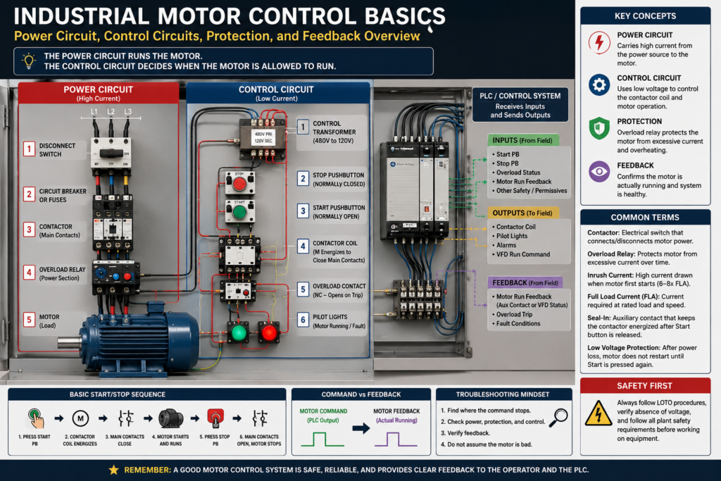
Power Circuit vs Control Circuit
One of the first concepts every automation technician must understand is the difference between the power circuit and the control circuit.
Power Circuit
The power circuit is the part of the system that carries the current used by the motor.
Typical power circuit components include:
- L1, L2, L3 incoming three-phase power
- Disconnect switch
- Fuses or circuit breaker
- Contactor main contacts
- Overload relay power section
- Motor leads T1, T2, T3
- Motor windings
The power circuit does the heavy work. It supplies the actual energy that makes the motor rotate.
Control Circuit
The control circuit is the part of the system that decides when the motor should turn on or off.
Typical control circuit components include:
- Stop pushbutton
- Start pushbutton
- Contactor coil
- Auxiliary contact
- Overload auxiliary contact
- PLC output
- Relay contacts
- Limit switches
- Pressure switches
- Float switches
- HMI command logic
A simple way to remember it:
The power circuit runs the motor.
The control circuit decides when the motor is allowed to run.
The motor control material explains that ladder diagrams often show the control circuit separately from the power circuit, because ladder diagrams are easier to follow when troubleshooting circuit operation.
The Basic Motor Starter
A motor starter is one of the most common devices used in industrial motor control.
A basic magnetic motor starter usually includes:
- Contactor
- Overload relay
- Auxiliary contacts
The contactor switches the motor power on and off. The overload relay protects the motor from excessive current over time. The auxiliary contacts are used in the control circuit for seal-in logic, status feedback, or interlocking.
A good way to think about it:
A contactor is the electrical switch.
An overload relay is the motor protection.
A starter is the contactor and overload working together.
What Is a Contactor?
A contactor is an electrically operated switching device. When the contactor coil is energized, it creates a magnetic field. This magnetic field pulls in the armature and closes the main contacts, allowing power to flow to the motor.
When the coil is de-energized, the contacts open and remove power from the motor.
Main parts of a contactor include:
- Coil
- Armature
- Main power contacts
- Auxiliary contacts
- Arc suppression area or arc chute, depending on design
The glossary defines a contact as the part of a contactor that makes and breaks the electrical connection, and it defines arcing as the condition where high voltage jumps across the open space between contacts.
This is important because contactors are mechanical devices. Over time, contacts can wear, burn, pit, or develop oxide buildup. That can cause voltage drop, overheating, intermittent operation, or motor starting problems.
What Is an Overload Relay?
An overload relay protects the motor from drawing too much current for too long.
A motor can draw excessive current because of:
- Mechanical jam
- Overloaded conveyor
- Pump problem
- Bearing failure
- Low voltage
- Phase loss
- Incorrect motor sizing
- Motor wiring issue
- Locked rotor condition
The glossary defines overload protection as a device or system that prevents an electric motor from drawing too much current, overheating, and burning out. It also defines locked rotor as a condition where the motor is so overloaded that the rotor cannot turn.
This is a key distinction:
| Device | Main Purpose |
|---|---|
| Fuse / Circuit Breaker | Protects against short circuits and high fault current |
| Overload Relay | Protects the motor from overheating due to excessive current over time |
| Contactor | Turns motor power on and off |
| PLC | Makes logic decisions, but does not replace motor protection |
The overload relay does not replace the breaker or fuse. Each protection device has a different job.
Inrush Current: Why Motors Draw High Current at Startup
When a motor first starts, it normally draws much higher current than it does while running.
This starting current is called inrush current.
The glossary explains that inrush current can be 6 to 8 times the normal running current when a motor is first switched on.
That means a motor with a running current of 10 amps may briefly pull 60 to 80 amps during startup.
This is why motor circuits require proper sizing and protection. It is also why large motors may use:
- Reduced-voltage starters
- Soft starters
- VFDs
- Star-delta starting
- Current-limiting methods
For small motors, across-the-line starting is common. For larger motors, starting current and mechanical stress become more important.
Across-the-Line Starter
An across-the-line starter connects the incoming power directly to the motor when the contactor closes.
This is the simplest and most common method for starting many general-purpose motors.
Basic sequence:
- Operator presses Start.
- Control circuit energizes the contactor coil.
- Main contacts close.
- Full voltage is applied to the motor.
- Motor starts and accelerates to running speed.
The glossary describes across-the-line as a general-purpose starter that connects incoming power directly to the motor.
Across-the-line starting is simple, but it produces high inrush current and full starting torque. That may be acceptable for many applications, but not for every machine.
Full Load Current
Full Load Current, often called FLA, is the current required by the motor to produce full-load torque at rated speed.
This value is extremely important because it is used for:
- Overload relay settings
- VFD motor parameters
- Motor starter sizing
- Troubleshooting current draw
- Comparing actual load vs rated load
The glossary defines full load current as the current required by the motor to produce full-load torque at the motor’s rated speed.
As an automation technician, always check the motor nameplate. The nameplate gives critical information such as voltage, full-load amps, horsepower, RPM, phase, frequency, and service factor.
Motor Service Factor
Motor service factor tells how much extra load a motor can handle under specific conditions without overheating.
For example, a motor with a service factor of 1.15 can handle 15% more than its rated horsepower under proper operating conditions.
The glossary describes motor service factor as the amount of extra horsepower a motor can generate without overheating, commonly expressed as 1.15.
This does not mean the motor should always be operated above its rating. It is more like a margin, not a normal operating target.
Basic Start/Stop Logic
One of the most important motor control circuits is the Start/Stop circuit.
A typical three-wire Start/Stop circuit uses:
- Normally closed Stop pushbutton
- Normally open Start pushbutton
- Contactor coil
- Auxiliary seal-in contact
- Overload contact
Basic operation:
- Stop button is normally closed, allowing control power to pass.
- Operator presses Start.
- Contactor coil energizes.
- Main contacts close and motor starts.
- Auxiliary contact closes around the Start button.
- Operator releases Start, but the auxiliary contact keeps the coil energized.
- Pressing Stop opens the circuit and de-energizes the coil.
- Motor stops.
This auxiliary contact is often called the seal-in contact or holding contact.
Simple ladder concept:
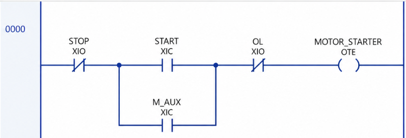
Memory or seal-in logic as the condition where pressing the Start button energizes the coil, closes the auxiliary contact, and creates a current path around the Start button until the Stop button breaks the circuit.
Low Voltage Protection
Three-wire Start/Stop control provides a useful safety behavior called low voltage protection.
If power is lost, the contactor drops out. When power returns, the motor does not automatically restart. The operator must press Start again.
Low voltage protection as a three-wire control setup where, after voltage drops and is restored, the contactor remains open.
This is important for equipment where automatic restart could create a hazard.
Two-Wire Control vs Three-Wire Control
Motor control circuits are often grouped into two basic styles:
| Type | Main Feature | Common Example |
|---|---|---|
| Two-wire control | Maintained contact controls the motor | Float switch, pressure switch |
| Three-wire control | Momentary Start/Stop with seal-in contact | Pushbutton station |
Two-Wire Control
Two-wire control uses a maintained device, such as a float switch or pressure switch. When the device closes, the motor runs. When it opens, the motor stops.
Common uses:
- Pump controlled by float switch
- Compressor controlled by pressure switch
- Exhaust fan controlled by thermostat
Three-Wire Control
Three-wire control uses momentary Start and Stop pushbuttons with a seal-in contact.
Common uses:
- Conveyor start/stop station
- Machine motor starter
- Operator-controlled motor
The MCTrainer lab manual includes separate units for two-wire controls and three-wire controls, showing that these are foundational motor control concepts.
Motor Command vs Motor Feedback
In modern automation, it is not enough to only command a motor. We also want to know if the motor actually started.
This is the difference between command and feedback.
| Signal | Meaning |
|---|---|
| Motor_Run_Command | The PLC or control circuit is telling the motor to run |
| Motor_Run_Feedback | A contact, sensor, or drive status proves the motor is actually running |
A motor command may turn on, but the motor may not run because of:
- Tripped overload
- Failed contactor coil
- Blown fuse
- Open control circuit
- VFD fault
- Bad output module
- Broken wire
- Mechanical jam
A professional PLC program should usually separate these ideas:
Operator Request → Motor Command → Physical Output → Motor FeedbackThis structure makes troubleshooting much easier.
Why Safety Comes First
Motor control systems involve dangerous voltage, moving machinery, stored energy, and mechanical hazards. Before working on motor circuits, technicians must follow plant safety procedures, lockout/tagout requirements, and qualified electrical work practices.
The motor control textbook emphasizes that electrical safety is the number one priority and covers shock hazards, PPE, grounding, bonding, lockout/tagout, and electrical codes.
A motor can hurt someone in more than one way:
- Electrical shock
- Arc flash
- Unexpected startup
- Rotating shaft
- Pinch point
- Moving conveyor
- Stored mechanical energy
- Stored electrical energy in VFD capacitors
Never troubleshoot a motor control panel casually. Always know what voltage is present, what energy sources exist, and what procedure is required before touching equipment.
Common Motor Control Terms
Here are some important terms every automation technician should know:
| Term | Simple Meaning |
|---|---|
| Contactor | Electrically controlled switch used to connect/disconnect motor power |
| Starter | Motor control device, commonly contactor plus overload |
| Overload | Excessive load or current condition on a motor |
| Overload Relay | Device that trips when motor current is too high for too long |
| Inrush Current | High current drawn when motor first starts |
| Full Load Current | Current required at rated motor load |
| Locked Rotor | Motor cannot turn even though current is being applied |
| Control Circuit | Circuit that controls the contactor or relay |
| Power Circuit | Circuit that carries motor current |
| Auxiliary Contact | Extra contact used for seal-in, feedback, or interlocking |
| Trip Class | Time rating for overload trip behavior under high current |
Practical Troubleshooting Mindset
When a motor does not start, do not immediately assume the motor is bad.
A better approach is to follow the control path step by step:
- Is the disconnect ON?
- Are fuses or breakers good?
- Is control voltage present?
- Is the E-Stop or safety circuit OK?
- Is the overload reset and healthy?
- Is the Start command reaching the PLC or control circuit?
- Is the PLC output turning on?
- Is the contactor coil receiving voltage?
- Are the contactor main contacts closing?
- Is power reaching the motor terminals?
- Is the motor drawing normal current?
- Is the mechanical load free to move?
A strong troubleshooting phrase:
Find where the command stops.
This means you trace the signal from the operator request all the way to the motor power circuit.
Final Thoughts
Industrial motor control is a core skill for automation technicians. Once you understand the relationship between the power circuit, control circuit, contactor, overload relay, Start/Stop logic, and motor feedback, troubleshooting becomes much more organized.
The goal is not only to make a motor run. The goal is to make it run safely, reliably, and with enough feedback to know what is happening in the machine.
As this series continues, we will go deeper into Start/Stop circuits, two-wire and three-wire control, contactors, overloads, motor nameplates, three-phase motors, reversing starters, HOA control, VFDs, PLC integration, and real troubleshooting methods used in industrial environments.