4. PLC Inputs and Outputs Explained
A PLC controls a machine by using inputs and outputs.
In simple terms:
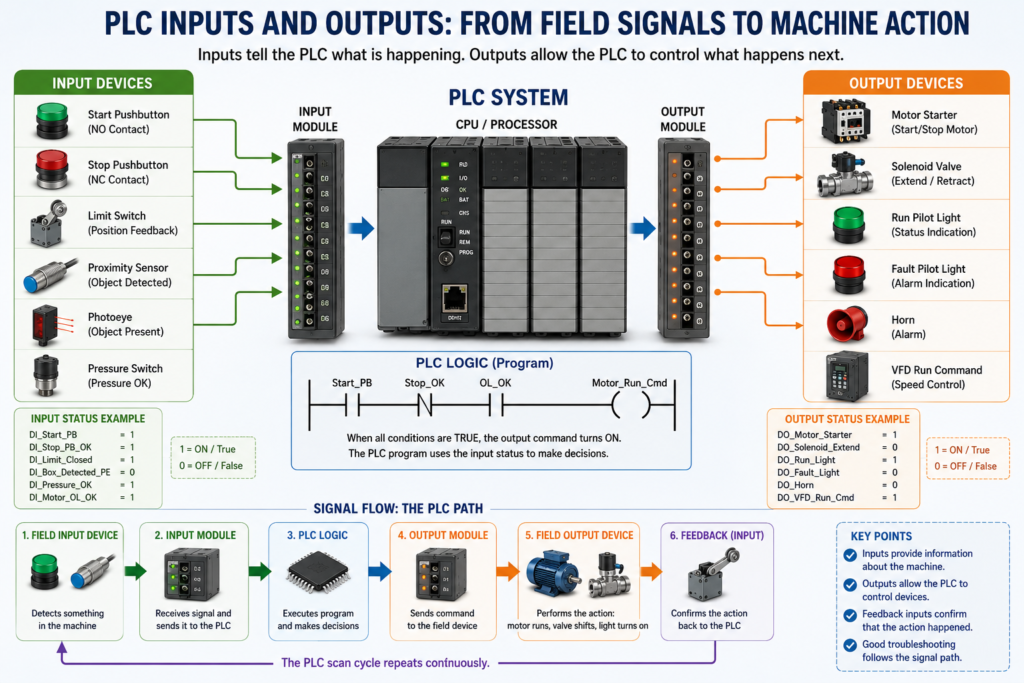
Inputs tell the PLC what is happening.
Outputs allow the PLC to control what happens next.
A PLC does not operate a machine by itself. It depends on real-world devices connected to its input and output modules.
A basic PLC control path looks like this:
Field Input Device → PLC Input Module → PLC Logic → PLC Output Module → Field Output DeviceFor an Automation Technician, understanding this path is essential. Many PLC troubleshooting problems are not actually programming problems. They are often caused by input devices, output devices, wiring, field power, fuses, relays, sensors, or bad connections.
According to Programmable Logic Controllers, 6th Edition, the I/O system forms the interface between external field devices and the PLC controller. Input devices such as pushbuttons, limit switches, and sensors are wired to input terminals, while output devices such as motor starters, solenoid valves, and indicator lights are wired to output terminals.
What Is a PLC Input?
A PLC input is a signal coming from a field device into the PLC.
Inputs are used to tell the PLC the status of the machine or process.
Examples:
Is the Start pushbutton pressed?
Is the Stop pushbutton healthy?
Is the limit switch made?
Is the photoeye blocked?
Is the pressure switch active?
Is the motor overload tripped?
Is the VFD faulted?
Is the safety relay OK?
The PLC uses these input signals to make decisions in the program.
Common PLC Input Devices
PLC input devices can include:
Pushbuttons
Selector switches
Limit switches
Proximity sensors
Photoelectric sensors
Pressure switches
Level switches
Temperature switches
Flow switches
Motor overload auxiliary contacts
VFD status contacts
Safety relay auxiliary contacts
Encoder signals
Analog transmitters
These devices are normally installed in the field, on the machine, or inside the control panel.
Input Example
Imagine a simple motor start circuit.
The PLC may need these inputs:
Start_PB
Stop_PB_OK
Motor_Overload_OK
E_Stop_OK
Motor_Feedback
The PLC logic may say:
IF Start_PB is pressed
AND Stop_PB_OK is true
AND Motor_Overload_OK is true
AND E_Stop_OK is true
THEN allow the motor to start
In this case, the PLC depends on the input devices to know whether it is safe and correct to start the motor.
How a PLC Input Module Works
The input module receives the electrical signal from the field device and converts it into a logic signal the PLC processor can use.
Example:
24 VDC from sensor → Input module detects voltage → PLC sees logic 1
No voltage from sensor → Input module does not detect signal → PLC sees logic 0
In basic digital logic:
1 = ON / True
0 = OFF / False
So if a proximity sensor turns ON, the PLC input bit may become true.
Example tag:
DI_Box_Detected = 1If the sensor turns OFF:
DI_Box_Detected = 0What Is a PLC Output?
A PLC output is a command sent from the PLC to a field device.
Outputs allow the PLC to control the machine.
Examples:
Turn on a motor starter
Energize a solenoid valve
Turn on a pilot light
Start a VFD
Sound a horn
Open a valve
Turn on a stack light
Activate a relay
The PLC program decides when the output should turn ON or OFF.
Common PLC Output Devices
PLC output devices can include:
Motor starters
Contactors
Relays
Interposing relays
Solenoid valves
Pilot lights
Stack lights
Horns
Buzzers
VFD run commands
Valve actuators
Heaters
Small motors
Signal lamps
The output module does not “think.” It simply follows the output command from the PLC program.
Output Example
Imagine the PLC wants to run a conveyor.
The program may generate this command:
Conveyor_Run_Cmd = 1Then the output module energizes the physical output:
DO_Conveyor_Starter = ONThe field result:
Motor starter coil energizes
Contactor pulls in
Conveyor motor starts running
This is the basic relationship between logic and real-world machine action.
Input vs Output: Simple Difference
| Type | Direction | Purpose | Examples |
|---|---|---|---|
| Input | Field device to PLC | Tells the PLC what is happening | Pushbutton, sensor, limit switch |
| Output | PLC to field device | Allows the PLC to control something | Solenoid, relay, pilot light |
| Internal Bit | Inside PLC logic | Stores a logic condition | Start request, fault bit, permissive |
| Feedback Input | Field device to PLC | Confirms that an output action happened | Motor running feedback, valve open limit |
Digital Inputs and Outputs
Most beginner PLC applications use digital I/O.
Digital means the signal has only two states:
ON or OFF
1 or 0
True or False
Energized or de-energized
Examples of digital inputs:
Start pushbutton pressed or not pressed
Limit switch made or not made
Photoeye blocked or clear
Overload contact healthy or tripped
Examples of digital outputs:
Pilot light ON or OFF
Solenoid energized or de-energized
Motor starter ON or OFF
Horn ON or OFF
Digital I/O is also called discrete I/O.
Analog Inputs and Outputs
Analog signals are different from digital signals.
An analog signal represents a changing value, not just ON or OFF.
Common analog signals include:
4–20 mA
0–10 VDC
0–5 VDC
1–5 VDC
Analog inputs are used for process values such as:
Tank level
Pressure
Temperature
Flow
Weight
Speed
Position
pH
Conductivity
Example:
Pressure transmitter sends 4–20 mA to PLC
PLC converts signal into PSI
HMI displays pressure value
Analog outputs are used to control devices such as:
Control valves
VFD speed references
Positioners
Analog meters
Proportional valves
Example:
PLC sends 4–20 mA speed reference to VFD
VFD adjusts motor speed
Discrete I/O vs Analog I/O
| Type | Signal | Meaning | Example |
|---|---|---|---|
| Discrete Input | ON/OFF | Device status | Limit switch made |
| Discrete Output | ON/OFF | Command device | Solenoid ON |
| Analog Input | Variable value | Process measurement | 4–20 mA level transmitter |
| Analog Output | Variable command | Process control | 0–10 VDC speed reference |
Simple way to remember:
Discrete = status or command
Analog = measurement or variable control
Real-World PLC Input Path
A PLC input path may look like this:
Sensor → Field wiring → Terminal block → Input module → PLC input tag → Program logicExample:
Photoeye sensor detects box
24 VDC signal goes to input module
PLC input LED turns ON
PLC tag DI_Box_Detected becomes true
Program allows conveyor sequence to continue
This is why troubleshooting should follow the signal path.
Real-World PLC Output Path
A PLC output path may look like this:
PLC logic → Output tag → Output module → Terminal block → Field device → Machine actionExample:
PLC turns on DO_Solenoid_Extend
Output module LED turns ON
24 VDC is sent to solenoid coil
Solenoid valve shifts
Cylinder extends
Extended limit switch turns ON as feedback
A professional technician checks each step.
Input LED vs PLC Logic
The input LED on a PLC input module is very useful, but it does not tell the full story.
If the input LED is ON, it usually means the module is receiving the electrical signal.
But the machine may still not respond because:
The program is using a different tag
The input is inverted
The input is mapped through buffer logic
The input is disabled in manual mode
A permissive is missing
An interlock is active
A fault is latched
The output command is blocked
Important:
Input LED ON does not automatically mean the final output should turn ON.The input must still pass through the PLC logic.
Output LED vs Field Device
The output LED is also useful, but it does not prove the field device is working.
If the output LED is ON, the PLC is commanding the output.
But the field device may still not energize because of:
Blown fuse
Missing field power
Bad output relay
Bad solenoid coil
Bad contactor coil
Broken wire
Loose terminal
Bad neutral or common
Wrong voltage
Failed interposing relay
Mechanical failure
VFD fault
Important:
Output LED ON does not always mean the device is physically working.You still need to verify voltage and device operation in the field.
Why Feedback Inputs Matter
A PLC output command tells a device to operate.
A feedback input confirms that the device actually operated.
Example:
PLC Output Command:
DO_Motor_Starter = ON

Feedback Input:
DI_Motor_Running_FB = ON
These are not the same thing.
The PLC may command a motor to run, but the motor may fail to start.
Possible causes:
Contactor failed
Overload tripped
VFD faulted
Motor disconnected
Starter coil bad
Control voltage missing
Mechanical jam
That is why industrial PLC programs often use feedback logic.
Example:
IF Motor_Run_Cmd is ON
AND Motor_Running_FB does not turn ON within 3 seconds
THEN latch Motor_Failed_To_Start fault
This is a very important industrial concept.
Command vs Feedback
| Signal | Meaning | Example |
|---|---|---|
| Command | PLC is telling the device to operate | Motor_Run_Cmd |
| Output | Physical PLC output is energized | DO_Motor_Starter |
| Feedback | Field device confirms operation | DI_Motor_Running_FB |
| Fault | Expected feedback did not happen | Motor_Failed_To_Start |
Simple concept:
Command = what the PLC wants
Feedback = what actually happened
This difference is critical for troubleshooting.
Normally Open and Normally Closed Inputs
Many PLC input devices use either normally open or normally closed contacts.
Normally Open Contact
A normally open device is open when not actuated.
Example:
Start pushbuttonWhen the operator presses it, the contact closes and sends a signal to the PLC.
Normally Closed Contact
A normally closed device is closed when healthy or not actuated.
Example:
Stop pushbutton
Emergency stop auxiliary contact
Motor overload contact
Safety relay OK contact
Normally closed contacts are often used for stop or safety-related status because a broken wire or lost signal can cause the PLC to see the condition as not OK.
Example:
Stop_PB_OK = 1 when the stop circuit is healthy
Stop_PB_OK = 0 when stop is pressed or wire is broken
This makes troubleshooting and fail-safe design easier.
Input Naming Best Practice
Good tag names make PLC logic easier to understand.
Instead of using only raw addresses like:
Local:1:I.Data.0Use descriptive tags like:
DI_Start_PB
DI_Stop_PB_OK
DI_Door_Closed_LS
DI_Motor_OL_OK
DI_Box_Detected_PE
Common prefixes:
| Prefix | Meaning |
|---|---|
| DI | Digital Input |
| DO | Digital Output |
| AI | Analog Input |
| AO | Analog Output |
| Cmd | Command |
| FB | Feedback |
| OK | Healthy condition |
| Fault | Fault condition |
Good tag naming helps both programmers and maintenance technicians.
Output Naming Best Practice
For outputs, use clear names that describe the field device.
Examples:
DO_Motor_Starter
DO_Solenoid_Extend
DO_Run_Pilot_Light
DO_Fault_Horn
DO_StackLight_Red
DO_VFD_Run_Command
Avoid vague names like:
Output_1
Motor
Valve
Light
Clear names reduce confusion when troubleshooting online.
Input and Output Buffering
A professional PLC program often separates raw I/O from internal logic.
Input Buffering
Input buffering maps raw physical inputs into readable internal tags.
Example:
Local:1:I.Data.0 → DI_Start_PB
Local:1:I.Data.1 → DI_Stop_PB_OK
Local:1:I.Data.2 → DI_Box_Detected
This makes the rest of the logic cleaner.
Output Buffering
Output buffering maps internal command bits to physical outputs.
Example:
Motor_Run_Cmd → DO_Motor_Starter → Local:2:O.Data.0
Solenoid_Extend_Cmd → DO_Solenoid_Extend → Local:2:O.Data.1
This approach helps troubleshoot the logic step by step.
Recommended flow:
Raw Input → Input Buffer → Logic → Output Buffer → Physical OutputSimple Motor Control Example
Inputs
DI_Start_PB
DI_Stop_PB_OK
DI_Motor_OL_OK
DI_Motor_Running_FB
Internal Logic
Motor_Start_Request
Motor_Permissive_OK
Motor_Run_Cmd
Motor_Failed_To_Start_Fault
Outputs
DO_Motor_Starter
DO_Run_Pilot_Light
DO_Fault_Pilot_Light
Logic Explanation
If Start_PB is pressed
AND Stop_PB_OK is true
AND Motor_OL_OK is true
AND no motor fault is active
THEN turn on Motor_Run_Cmd
Then:
Motor_Run_Cmd turns on DO_Motor_StarterThen:
Motor_Running_FB confirms the starter actually pulled inIf feedback does not turn ON:
Motor_Failed_To_Start_Fault is latchedThis is a more industrial way to think about inputs and outputs.
Troubleshooting PLC Inputs
When an input is not working, check:
Is the field device actuated?
Is the correct voltage present at the device?
Is the wire connected to the correct terminal?
Is the input common present?
Is the input LED ON?
Is the PLC tag changing state?
Is the input normally open or normally closed?
Is the sensor PNP or NPN?
Is the module sinking or sourcing?
Is the input mapped correctly in logic?
A good technician does not jump straight to the PLC program. First, verify the electrical signal.
Troubleshooting PLC Outputs
When an output is not working, check:
Is the PLC logic commanding the output?
Is the output bit ON?
Is the output module LED ON?
Is field power available to the output module?
Is the output fuse good?
Is voltage present at the output terminal?
Is voltage present at the field device?
Is the neutral/common connected?
Is the relay, solenoid, or contactor coil good?
Is the device mechanically stuck?
Is there feedback proving operation?
Always separate the problem:
Logic problem?
Output module problem?
Field wiring problem?
Device problem?
Mechanical problem?
Common PLC I/O Problems
| Symptom | Possible Cause |
|---|---|
| Input LED does not turn ON | Bad sensor, missing voltage, broken wire, bad common |
| Input LED ON but logic false | Wrong tag, inverted logic, buffer issue, wrong routine |
| Output bit ON but output LED OFF | Module issue, disabled output, wrong mapping |
| Output LED ON but device OFF | Missing field power, blown fuse, bad coil, bad wire |
| Device turns ON unexpectedly | Logic error, forced output, shorted output, wrong wiring |
| Analog value unstable | Noise, bad shield, grounding issue, bad transmitter |
| Feedback missing | Device failed, auxiliary contact issue, wiring problem |
Automation Technician Notes
When troubleshooting PLC I/O, think in layers.
For inputs:
Field device → Wiring → Input module → PLC tag → LogicFor outputs:
Logic → PLC output tag → Output module → Wiring → Field device → FeedbackThis prevents guessing.
A professional technician proves each section before moving to the next one.
The most important question is not just:
Is the PLC input or output ON?The better questions are:
Is the signal physically present?
Is the PLC seeing it?
Is the logic using it correctly?
Is the output being commanded?
Is the field device actually responding?
Is feedback confirming the action?
That is the foundation of real PLC troubleshooting.
Key Terms
| Term | Meaning |
|---|---|
| Input | Signal coming from a field device into the PLC |
| Output | Command sent from the PLC to a field device |
| Field Device | Physical device connected to the PLC |
| Digital I/O | ON/OFF signal |
| Analog I/O | Variable signal such as 4–20 mA or 0–10 V |
| Input Module | Module that receives field signals |
| Output Module | Module that controls field devices |
| Input LED | Module indicator showing input electrical status |
| Output LED | Module indicator showing output command status |
| Feedback | Signal confirming that a device actually operated |
| Interposing Relay | Relay used between a PLC output and a larger load |
| Input Buffer | Logic area that maps raw inputs to internal tags |
| Output Buffer | Logic area that maps internal commands to physical outputs |
Quick Summary
Inputs tell the PLC what is happening.
Outputs allow the PLC to control the machine.
Digital I/O is ON/OFF.
Analog I/O is variable.
Input LEDs and output LEDs help troubleshooting, but they do not tell the full story.
Feedback confirms whether the commanded device actually operated.
For an Automation Technician, PLC I/O is one of the most important concepts to master.
Final Thoughts
PLC inputs and outputs are the connection between the real machine and the control program.
Inputs give the PLC information. Outputs allow the PLC to take action. Feedback proves whether the action actually happened.
When troubleshooting, always follow the complete path:
Input device → PLC logic → Output command → Field device → FeedbackThis method helps you troubleshoot safely, logically, and professionally.
Once you understand PLC I/O, ladder logic becomes much easier to read because every rung is connected to something real in the field.