Permissive vs Interlock in Ladder Logic
A Critical Difference Every PLC Technician Should Understand
In industrial automation, two words are often used together but do not mean exactly the same thing:
Permissive and Interlock
Both are used to control when a machine, motor, valve, door, conveyor, pump, or actuator is allowed to run. However, they serve different purposes in the logic.
Understanding this difference is very important when building professional PLC programs, troubleshooting equipment, or explaining logic to maintenance, engineering, and operations.
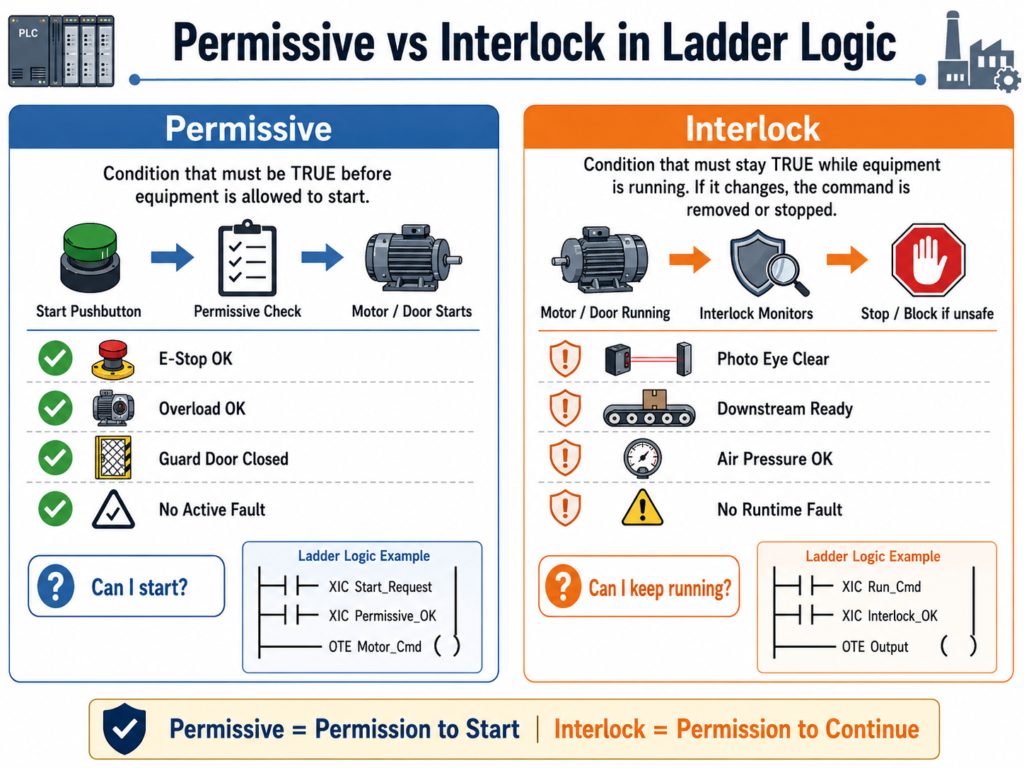
1. Simple Definition
What is a Permissive?
A permissive is a condition that must be true before a command is allowed to start.
In simple words:
A permissive gives permission to start.
Example:
A motor can start only if:
- E-Stop is healthy
- Overload is not tripped
- Guard door is closed
- System is in Auto mode
- No active fault exists
If all required conditions are good, the PLC allows the start command to continue.
What is an Interlock?
An interlock is a condition that can stop or block operation while the equipment is running.
In simple words:
An interlock protects the machine, process, or operator during operation.
Example:
A conveyor is already running, but if a downstream conveyor stops, the upstream conveyor must stop immediately to prevent product backup or a jam.
That downstream condition is an interlock.
2. Main Difference
| Concept | Permissive | Interlock |
|---|---|---|
| Main purpose | Allows equipment to start | Stops or blocks equipment during operation |
| Timing | Checked before starting | Checked while running |
| Logic role | Start enable condition | Runtime protection condition |
| Example | “Can I start?” | “Can I continue running?” |
| Typical use | Start circuit, command enable | Run circuit, output enable, fault logic |
| Operator expectation | Machine will not start if not ready | Machine may stop if unsafe or process condition changes |
3. Easy Way to Remember
A simple way to think about it:
Permissive = Permission to Start
Interlock = Permission to Continue
For example, imagine a garage door or industrial freezer door.
Before opening the door, the PLC may check:
- Is the system healthy?
- Is the motor overload okay?
- Is the E-Stop reset?
- Is the door not already fully open?
Those are permissives.
But while the door is closing, if the photo eye detects an obstruction, the PLC must stop the closing command.
That photo eye condition is an interlock.
4. Industrial Door Example
Let’s use an industrial door as an example.
The operator presses the Open Pushbutton.
Before the PLC allows the door to open, it should verify that certain conditions are true.
Open Permissives
The door may be allowed to open only if:
- The E-Stop circuit is healthy
- The motor overload is not tripped
- The door is not already fully open
- No active fault is present
- The close command is not active
- The system is not inhibited by a safety or process condition
Example tag names:
DI_EStop_OK
DI_Motor_OL_OK
DI_LS_Open_Position
Fault_Active
Close_Cmd
Open_Permissive
A basic open permissive may look like this:
Open_Permissive =
    DI_EStop_OK
AND DI_Motor_OL_OK
AND NOT DI_LS_Open_Position
AND NOT Fault_Active
AND NOT Close_Cmd
In ladder-style logic:
XIC DI_EStop_OK
XIC DI_Motor_OL_OK
XIO DI_LS_Open_Position
XIO Fault_Active
XIO Close_Cmd
OTE Open_Permissive
This rung does not open the door by itself.
It only says:
Conditions are good enough to allow an open request.
5. Open Request vs Open Command
In professional ladder logic, it is better to separate the operator request from the final command.
Operator Request
The request comes from the operator or HMI.
Open_Request = Operator wants to open the doorExample:
XIC PB_Open
OTE Open_Request
But the request alone should not energize the motor.
The PLC should check the permissive first.
Open Command
The command is the PLC decision after checking the request and permissives.
Open_Cmd = Open_Request AND Open_PermissiveLadder-style:
XIC Open_Request
XIC Open_Permissive
OTE Open_Cmd
This structure is much cleaner than placing every condition directly around the motor output.
6. Where the Interlock Comes In
Now let’s say the door is closing.
If the photo eye detects an object, the door should stop closing.
That condition should not just be treated as a start permissive. It is a runtime interlock.
Example:
Close_Interlock_OK =
    NOT PhotoEye_Blocked
AND DI_EStop_OK
AND DI_Motor_OL_OK
AND NOT Fault_Active
Ladder-style:
XIO DI_PhotoEye_Blocked
XIC DI_EStop_OK
XIC DI_Motor_OL_OK
XIO Fault_Active
OTE Close_Interlock_OK
Then the close command should depend on the interlock:
XIC Close_Request
XIC Close_Permissive
XIC Close_Interlock_OK
OTE Close_Cmd
The important idea is this:
A permissive allowed the close command to start, but the interlock decides if it is still safe or valid to continue closing.
7. Practical Example: Door Closing Logic
For an industrial door, closing logic may require:
Close Permissives
Before closing:
- E-Stop healthy
- Motor overload okay
- Door is not already fully closed
- No active fault
- Open command is not active
- System is allowed to close
Close_Permissive =
    DI_EStop_OK
AND DI_Motor_OL_OK
AND NOT DI_LS_Closed_Position
AND NOT Fault_Active
AND NOT Open_Cmd
Close Interlocks
While closing:
- Photo eye must not be blocked
- E-Stop must remain healthy
- Motor overload must remain okay
- No runtime fault should occur
Close_Interlock_OK =
    NOT DI_PhotoEye_Blocked
AND DI_EStop_OK
AND DI_Motor_OL_OK
AND NOT Fault_Active
Final Close Command
Close_Cmd =
    Close_Request
AND Close_Permissive
AND Close_Interlock_OK
This gives the logic a professional structure:
Request → Permissive → Interlock → Command → Output8. Important Ladder Logic Concept
A common beginner mistake is putting every condition in one big rung.
Example of messy logic:
PB_Close
AND NOT Door_Closed
AND EStop_OK
AND Overload_OK
AND NOT PhotoEye
AND NOT Fault
AND Auto_Mode
AND NOT Open_Cmd
OTE Motor_Close_Output
This may work, but it becomes harder to troubleshoot.
A better industrial structure is:
Rung 1: Build Close_Request
Rung 2: Build Close_Permissive
Rung 3: Build Close_Interlock_OK
Rung 4: Build Close_Cmd
Rung 5: Map Close_Cmd to physical output
This makes the program easier to read, test, and troubleshoot.
9. Why This Matters in Troubleshooting
When equipment does not start, the technician should ask:
“What permissive is missing?”
Examples:
- Is the E-Stop OK?
- Is the overload reset?
- Is the system in Auto?
- Is a limit switch made?
- Is there an active fault?
- Is another command blocking it?
When equipment starts but then stops, the technician should ask:
“What interlock dropped out?”
Examples:
- Did a photo eye get blocked?
- Did downstream equipment stop?
- Did air pressure drop?
- Did a safety gate open?
- Did the motor feedback fail?
- Did the process condition change?
This troubleshooting mindset helps you diagnose the logic faster.
10. Motor Example
Let’s use a conveyor motor.
Start Permissives
The conveyor may start only if:
EStop_OK
Motor_OL_OK
Guard_Closed
Drive_Ready
No_Fault
Auto_Mode
This creates:
Motor_Start_PermissiveExample:
XIC EStop_OK
XIC Motor_OL_OK
XIC Guard_Closed
XIC Drive_Ready
XIO Fault_Active
XIC Auto_Mode
OTE Motor_Start_Permissive
Runtime Interlocks
While the conveyor is running, it may need to stop if:
- Downstream conveyor is not running
- Product jam is detected
- VFD fault occurs
- Motor feedback is lost
- Emergency stop drops out
This creates:
Motor_Run_Interlock_OKExample:
XIC Downstream_Ready
XIO Product_Jam
XIC Drive_Ready
XIC Motor_Feedback_OK
XIC EStop_OK
OTE Motor_Run_Interlock_OK
Final Motor Command
XIC Motor_Start_Request
XIC Motor_Start_Permissive
XIC Motor_Run_Interlock_OK
OTE Motor_Run_Cmd
11. Permissive vs Interlock vs Fault
Another important concept is knowing when an interlock should become a fault.
Not every interlock needs to latch a fault.
Some conditions are normal process stops.
For example:
Downstream_Ready = OFFThis may simply stop the upstream conveyor. It may not be a fault.
But some conditions should create a latched fault.
Example:
Motor_Run_Cmd = ON
AND Motor_Feedback = OFF
FOR 3 seconds
This should probably generate:
Motor_Feedback_FaultBecause the PLC commanded the motor to run, but the feedback did not confirm actual operation.
Example: Fault Logic
XIC Motor_Run_Cmd
XIO Motor_Feedback
TON Motor_FB_Fault_Timer 3 sec
Then:
XIC Motor_FB_Fault_Timer.DN
OTE Motor_Feedback_Fault
In many real systems, the fault would be latched:
XIC Motor_FB_Fault_Timer.DN
OTL Motor_Feedback_Fault
And reset with a fault reset pushbutton:
XIC Fault_Reset_PB
OTU Motor_Feedback_Fault
12. Recommended Naming Convention
Good tag names make the difference clear.
Permissive Tags
Use names like:
Open_Permissive
Close_Permissive
Motor_Start_Permissive
Pump_Start_Permissive
Valve_Open_Permissive
Auto_Start_Permissive
Interlock Tags
Use names like:
Close_Interlock_OK
Open_Interlock_OK
Motor_Run_Interlock_OK
Pump_Run_Interlock_OK
Conveyor_Interlock_OK
Process_Interlock_OK
Fault Tags
Use names like:
Motor_Overload_Fault
Motor_Feedback_Fault
Door_Travel_Timeout_Fault
PhotoEye_Blocked_Alarm
Drive_Not_Ready_Fault
13. Recommended Logic Structure
A professional PLC routine can be organized like this:
1. Input Buffering
2. Mode Selection
3. Requests
4. Permissives
5. Interlocks
6. Commands
7. Fault Logic
8. Alarm Logic
9. Output Buffering
10. HMI Status Bits
This type of structure makes the logic easier to troubleshoot and easier to explain.
14. Example Structure for an Industrial Door
Input Buffering
DI_Open_PB
DI_Close_PB
DI_Stop_PB
DI_EStop_OK
DI_Motor_OL_OK
DI_LS_Open_Position
DI_LS_Closed_Position
DI_PhotoEye_Clear
Requests
Open_Request
Close_Request
Stop_Request
AutoClose_Request
Permissives
Open_Permissive
Close_Permissive
AutoClose_Permissive
Interlocks
Open_Interlock_OK
Close_Interlock_OK
Motion_Interlock_OK
Commands
Open_Cmd
Close_Cmd
Motor_Up_Cmd
Motor_Down_Cmd
Outputs
DO_Motor_Open
DO_Motor_Close
DO_Open_Light
DO_Close_Light
DO_Fault_Light
15. Example Rung Comments
Good rung comments should explain the purpose of the rung, not just repeat the contacts.
Poor Comment
Open PB and permissive turns on Open Cmd.Better Comment
Allows the door to open only when the operator requests open and all required start conditions are healthy.Better Comment for Interlock
Removes the close command if the photo eye detects an obstruction or a runtime safety condition becomes invalid.Better Comment for Fault
Generates a latched motor feedback fault if the motor is commanded to run but feedback is not detected within the allowed time.16. Common Mistakes
Mistake 1: Treating every condition as a permissive
Some conditions only matter before starting.
Other conditions must remain true while running.
Do not mix everything together without thinking about timing and purpose.
Mistake 2: Not separating request and command
The pushbutton request should not directly drive the output.
Better structure:
Pushbutton → Request → Permissive → Interlock → Command → OutputMistake 3: Using raw inputs everywhere
Do not use raw inputs all over the program.
Better:
Raw Input → Input Buffer → Debounced/Validated Input → LogicExample:
Local:1:I.Data.0 → DI_PhotoEye_Clear → PhotoEye_Clear_ValidMistake 4: Making interlocks too hidden
If an interlock stops equipment, the operator should know why.
Use HMI status or alarm bits when appropriate.
Example:
Close_Inhibited_By_PhotoEye
Close_Inhibited_By_Overload
Close_Inhibited_By_EStop
Close_Inhibited_By_Fault
This helps maintenance and operators quickly understand why the machine is not moving.
17. Technician Troubleshooting Method
When troubleshooting a machine, use this order:
Step 1: Is there a request?
Check if the PLC sees the operator command.
Example:
Open_Request = ON?
Close_Request = ON?
Start_Request = ON?
If the request is not turning on, check:
- Pushbutton
- HMI button
- Input card
- Communication
- Mode selection
Step 2: Is the permissive true?
If the request is ON but the command is not turning on, check:
Open_Permissive
Close_Permissive
Motor_Start_Permissive
Find which required condition is missing.
Step 3: Is the interlock OK?
If the command starts and drops out, check:
Close_Interlock_OK
Motor_Run_Interlock_OK
Process_Interlock_OK
Find which runtime condition changed.
Step 4: Is there a fault?
Check for latched or active faults:
Motor_Overload_Fault
Drive_Fault
Feedback_Fault
Travel_Timeout_Fault
Step 5: Is the physical output energizing?
Finally, check:
DO_Motor_Start
DO_Open_Output
DO_Close_Output
Then verify the real-world device:
- Output card LED
- Relay
- Contactor
- VFD input
- Wiring
- Field device
18. Final Industrial Rule
A good PLC program should clearly answer these questions:
Did the operator request it?
Is the machine allowed to start?
Is it still allowed to continue running?
Did the PLC command the output?
Did the field device actually respond?
This is why separating requests, permissives, interlocks, commands, faults, and outputs is so powerful.
Final Thoughts
The difference between a permissive and an interlock may seem small at first, but it is very important in real industrial PLC programming.
A permissive answers:
“Are conditions good enough to start?”
An interlock answers:
“Are conditions still good enough to continue?”
When this difference is clearly designed in ladder logic, the program becomes easier to troubleshoot, safer to operate, and more professional.
For technicians learning PLC programming, this is one of the most important concepts to master because it improves both logic design and real-world troubleshooting.
A strong ladder logic program is not only about turning outputs on and off. It is about controlling machines in a structured, safe, and understandable way.