3. Reading Motor Control Drawings: Ladder, Wiring, Single-Line, and Block Diagrams (Series Post 3 of 22)
Wiring Diagrams, Ladder Diagrams, Single-Line Diagrams, and Block Diagrams
Introduction
Reading motor control drawings is one of the most important skills for an automation technician. A motor control panel may look complicated when you first open it: wires, contactors, overloads, pushbuttons, relays, terminal blocks, PLC modules, and motor leads everywhere. But the drawings are the map.
A good technician does not just look at the panel and guess. A good technician compares the physical components with the electrical drawings and follows the circuit step by step.
Motor control drawings help you understand:
- How the circuit is supposed to work
- Where power comes from
- How the motor is started and stopped
- Which devices are in series or parallel
- Where the control voltage goes
- Which contact belongs to which coil
- How to troubleshoot when the motor does not run
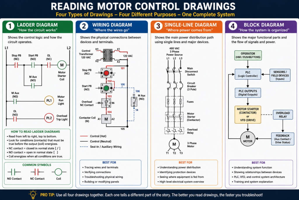
In industrial motor control, the most common drawings you will see are ladder diagrams, wiring diagrams, single-line diagrams, and block diagrams. Each one has a different purpose.
Why Motor Control Drawings Matter
A motor control circuit is not only wires and devices. It is a system. Drawings show how that system is connected and how it should operate.
Different electrical drawings are used when working with motors and control circuits, and that understanding symbols and equipment operation is necessary to read these drawings correctly.
This is important because the same motor circuit can be shown in different ways depending on what you need to understand.
For example:
| Drawing Type | Best For |
|---|---|
| Ladder diagram | Understanding circuit operation |
| Wiring diagram | Tracing physical wires and terminals |
| Single-line diagram | Understanding the main power path |
| Block diagram | Understanding major system functions |
A technician should not treat all drawings the same. Each drawing answers a different question.
1. Ladder Diagrams
A ladder diagram shows the electrical logic of a circuit. It focuses on how the circuit operates, not necessarily where the components are physically located.
Ladder diagrams are called “ladder” diagrams because they look like a ladder:
- Two vertical rails
- Horizontal rungs between the rails
- Control devices on the rungs
- Loads or coils usually on the right side
The MCTrainer material explains that ladder diagrams are one of the primary ways of communicating the language of control and that they consist of lines and symbols.
Basic Ladder Diagram Structure
L1                                                        L2
|                                                         |
|----[/ Stop PB ]----[ Start PB ]----[/ OL ]----( M )-----|
|                         |                               |
|                         |----[ M Aux ]------------------|
|                                                         |
In this example:
- L1 and L2 are the control power rails.
- Stop PB is a normally closed stop pushbutton.
- Start PB is a normally open start pushbutton.
- OL is a normally closed overload contact.
- M is the motor starter coil.
- M Aux is the seal-in auxiliary contact.
How to Read a Ladder Diagram
Read a ladder diagram like a book:
Left to right, top to bottom.
Ladder diagrams are designed to be read starting at the top left, moving left to right, and then continuing down.
A simple way to think about it:
Conditions on the left → Output/load on the rightExample:
Stop OK + Start Pressed + Overload OK = Motor Coil EnergizedNormally Open and Normally Closed Contacts
One of the biggest beginner challenges is understanding normally open and normally closed contacts.
Normally Open Contact
A normally open contact is open in its normal/de-energized state.
[ Start PB ]It closes when the device is actuated.
Example:
- A Start pushbutton is usually normally open.
- Pressing Start closes the contact.
- Current can flow.
Normally Closed Contact
A normally closed contact is closed in its normal/de-energized state.
[/ Stop PB ]It opens when the device is actuated.
Example:
- A Stop pushbutton is usually normally closed.
- Pressing Stop opens the contact.
- The motor control circuit drops out.
This is extremely important in motor control because Stop buttons, overload contacts, and safety devices are often wired normally closed so that a broken wire or open circuit stops the machine.
Understanding Rungs
A rung is one horizontal circuit path from the left rail to the right rail.
Each rung usually controls one output or function.
Example:
Rung 1: Motor starter coil
Rung 2: Motor run pilot light
Rung 3: Fault pilot light
The motor control textbook explains that rung numbering helps read larger ladder diagrams, especially when the circuit becomes more complex.
Example Rung
L1 ----[/ Stop PB ]----[ Start PB ]----[/ OL ]----( M )---- L2This rung means:
If Stop is closed,
and Start is pressed,
and Overload is not tripped,
then energize motor starter coil M.
Coils and Associated Contacts
In motor control, a coil and its contacts are related.
For example, a contactor coil may be labeled:
MAny auxiliary contact operated by that same contactor may also be labeled:
M Auxor:
M1This tells you that when the M coil energizes, the M auxiliary contact changes state.
The motor control textbook explains that a common method of identifying relay coils and their associated contacts is to place letters in the coil symbol and use the same letters next to contacts controlled by that coil.
Example
L1 ----[/ Stop ]----[ Start ]----[/ OL ]----( M )
              |----[ M Aux ]----|
Here:
- Pressing Start energizes coil M.
- Coil M closes the M Aux contact.
- The M Aux contact seals in the circuit.
That is the basic Start/Stop seal-in circuit.
Series and Parallel Logic
Motor control drawings also help you understand AND logic and OR logic.
Series = AND Logic
Devices wired in series must all be true/closed for the output to energize.
L1 ----[ Safety OK ]----[ Overload OK ]----[ Start ]----( Motor )This means:
Safety OK AND Overload OK AND Start = Motor ONCommon series devices:
- Stop pushbuttons
- E-Stops
- Overload contacts
- Safety contacts
- Permissives
- Interlocks
Parallel = OR Logic
Devices wired in parallel provide alternate paths.
L1 ----[ Start PB ]----( M )
       |
       |----[ M Aux ]---
This means:
Start PB OR M Aux can complete the circuit path.The MCTrainer material shows AND logic as series conditions and OR logic as parallel branches in ladder diagrams.
2. Wiring Diagrams
A wiring diagram shows the physical wiring connections between devices.
Unlike a ladder diagram, a wiring diagram is more focused on actual terminals, wire numbers, device locations, and point-to-point connections.
The motor control textbook explains that wiring diagrams are used to show point-to-point wiring between components and may show physical relationships, wire identification numbers, and/or color coding.
What Wiring Diagrams Are Best For
Wiring diagrams are useful when you need to:
- Trace a wire
- Verify a terminal connection
- Find a loose wire
- Check field wiring
- Wire a replacement device
- Identify where a pushbutton connects
- Confirm terminal block connections
- Compare physical panel wiring to documentation
Example
A wiring diagram may show something like:
Wire 101: Control transformer X1 → Stop PB terminal 1
Wire 102: Stop PB terminal 2 → Start PB terminal 1
Wire 103: Start PB terminal 2 → Overload NC contact
Wire 104: Overload NC contact → Contactor coil A1
Wire 105: Contactor coil A2 → Control transformer X2
This helps you physically trace the circuit in the panel.
Ladder Diagram vs Wiring Diagram
This is one of the most important distinctions.
| Feature | Ladder Diagram | Wiring Diagram |
|---|---|---|
| Main purpose | Shows how the circuit works | Shows how the circuit is physically wired |
| Best for | Understanding logic and troubleshooting sequence | Tracing wires and terminals |
| Device location | Not necessarily physical | Closer to physical layout |
| Easy to understand operation? | Yes | Not always |
| Easy to wire from? | Sometimes | Yes |
| Common use | Troubleshooting logic | Installation and wire tracing |
A simple way to remember:
Ladder diagrams explain the operation.
Wiring diagrams explain the connections.
Practical Example: Same Circuit, Two Views
Ladder View
L1 ----[/ Stop ]----[ Start ]----[/ OL ]----( M )
              |----[ M Aux ]----|
L2
This tells you how the circuit works.
Wiring View
X1 → Stop PB terminal 1
Stop PB terminal 2 → Start PB terminal 1
Start PB terminal 2 → Overload NC terminal 95
Overload NC terminal 96 → Contactor coil A1
Contactor coil A2 → X2
M Aux terminal 13/14 wired around Start PB
This tells you where wires physically go.
Both views are important.
3. Single-Line Diagrams
A single-line diagram, also called a one-line diagram, shows the main power distribution path using one line to represent a multi-phase circuit.
The motor control textbook explains that a single-line diagram uses symbols and a single line to show major components of an electric circuit, often serving as a simplified map of the motor installation.
What Single-Line Diagrams Show
Single-line diagrams may show:
- Power source
- Transformer
- Main breaker
- MCC
- Feeder breaker
- Disconnect
- Fuses
- Motor starter
- VFD
- Motor
- Grounding
- Protection devices
Example Single-Line Motor Circuit
480 VAC 3PH Source
        |
Main Breaker
        |
MCC Bucket
        |
Motor Starter
        |
Overload Protection
        |
3PH Motor
A single-line diagram does not usually show every control wire. It gives you the big picture of the power system.
Best Use
Single-line diagrams are best when you need to answer:
- Where does this motor get power from?
- Which breaker feeds this starter?
- Is this motor fed from an MCC?
- Is there a transformer involved?
- What protection devices are upstream?
- What is the main power path?
4. Block Diagrams
A block diagram shows major functional sections of a system using blocks instead of detailed wiring symbols.
The motor control textbook explains that block diagrams represent major functional parts of complex electrical or electronic systems, where each block represents a circuit or function.
Example: VFD Block Diagram
A VFD can be shown as:
3-Phase AC Input → Rectifier → DC Bus → Inverter → MotorThis does not show every internal component, but it explains the function.
What Block Diagrams Are Best For
Block diagrams are useful for understanding:
- VFD operation
- PLC system architecture
- HMI to PLC communication
- Networked control systems
- Sensor to controller to output relationships
- High-level machine operation
Example: PLC Motor Control Block Diagram
Start PB / Sensors / Overload
        ↓
PLC Inputs
        ↓
PLC Logic
        ↓
PLC Output
        ↓
Contactor Coil or VFD Run Command
        ↓
Motor
        ↓
Feedback to PLC
This type of diagram is excellent for explaining automation systems in a blog post because it shows the system flow clearly.
Common Motor Control Symbols
Here are some common symbols and abbreviations you will see in motor control drawings.
| Symbol / Abbreviation | Meaning |
|---|---|
| L1, L2, L3 | Incoming power lines |
| T1, T2, T3 | Motor terminals/load side |
| M | Motor starter or contactor coil |
| OL | Overload relay/contact |
| PB | Pushbutton |
| CR | Control relay |
| LS | Limit switch |
| PL | Pilot light |
| FWD | Forward |
| REV | Reverse |
| HOA | Hand-Off-Auto |
| XFMR | Transformer |
| NC | Normally closed |
| NO | Normally open |
Common motor abbreviations such as CR for control relay, OL for overload relay, PB for pushbutton, PL for pilot light, L1/L2/L3 for power line connections, and T1/T2/T3 for motor terminal connections.
Reading a Motor Starter Drawing Step by Step
When reading a motor starter drawing, use a consistent method.
Step 1: Identify the Power Source
Look for:
L1, L2, L3Ask:
- What voltage is feeding the motor?
- Is it single-phase or three-phase?
- Where does the power come from?
Step 2: Follow the Power Circuit
Trace the high-current path:
L1/L2/L3 → Disconnect → Breaker/Fuses → Contactor → Overload → T1/T2/T3 → MotorAsk:
- Are there fuses?
- Is there a disconnect?
- Does the circuit use a contactor or VFD?
- Where is the overload located?
- What terminals feed the motor?
Step 3: Identify the Control Voltage
Look for:
Control transformer
24 VDC power supply
120 VAC control power
Ask:
- What voltage controls the coil?
- Is it 120 VAC?
- Is it 24 VDC?
- Is one side grounded?
- Are there control fuses?
Step 4: Follow the Stop Circuit
Stop devices are usually in series.
Look for:
- Stop pushbutton
- E-Stop contact
- Overload NC contact
- Safety relay contact
- Guard switch
- Permissive contact
Typical logic:
Stop OK AND Overload OK AND Safety OK = Control circuit allowedStep 5: Find the Start Command
Start devices may be:
- Start pushbutton
- PLC output
- HMI command
- Float switch
- Pressure switch
- HOA selector switch
- Auto request
Ask:
- What starts the motor?
- Is it local or automatic?
- Is there a seal-in contact?
- Is the PLC involved?
Step 6: Find the Coil
Look for the load on the rung:
( M )or:
Contactor Coil A1/A2Ask:
- What energizes this coil?
- What contacts does this coil operate?
- Does this coil close main contacts?
- Does it have auxiliary feedback?
Step 7: Find the Feedback
Modern motor systems often include feedback.
Look for:
- Auxiliary contact from contactor
- VFD running output
- Motor current switch
- PLC input
- Motor_Run_FB tag
Feedback answers the question:
Did the motor actually run, or did we only command it to run?
Troubleshooting with Drawings
When troubleshooting, drawings help you avoid guessing.
Example Problem
The motor does not start.
Use the Ladder Diagram
Check the logic:
- Is Stop closed?
- Is Start closing?
- Is overload contact closed?
- Is safety OK?
- Is the coil command present?
Use the Wiring Diagram
Check the physical circuit:
- Is control voltage present at the Stop PB?
- Does voltage leave the Stop PB?
- Does voltage reach the Start PB?
- Does voltage reach the overload contact?
- Does voltage reach coil A1?
- Is A2 connected to neutral/common?
Use the Single-Line Diagram
Check the power source:
- Is the feeder breaker ON?
- Is the disconnect ON?
- Are all three phases present?
- Is the MCC bucket energized?
Use the Block Diagram
Check the system relationship:
- Is the PLC receiving inputs?
- Is logic commanding the output?
- Is the starter or VFD receiving the command?
- Is feedback returning to the PLC?
Common Mistakes When Reading Drawings
Mistake 1: Thinking the Ladder Diagram Shows Physical Location
A ladder diagram shows logic, not always physical layout.
Two devices may be next to each other on the ladder diagram but physically located far apart in the plant.
Mistake 2: Ignoring Normally Closed Contacts
A normally closed contact may look confusing at first. Remember: normally closed means closed in its normal state, not necessarily closed right now.
Mistake 3: Not Matching Coil and Contact Labels
If a contact is labeled M, it is controlled by the M coil.
If a contact is labeled CR1, it is controlled by relay coil CR1.
Mistake 4: Troubleshooting Only from the PLC
The PLC may show an output ON, but the motor may still not run because of a power circuit issue.
Mistake 5: Not Using Wire Numbers
Wire numbers are extremely helpful. If wire 104 leaves the overload contact and goes to coil A1, use that number to physically trace the circuit.
Practical Technician Rule
Use this rule:
Ladder diagram = How it works
Wiring diagram = Where the wires go
Single-line diagram = Where power comes from
Block diagram = How the system is organized
This simple rule makes reading drawings much easier.
Example: Reading a Basic Motor Starter Circuit
Power Circuit
L1/L2/L3
   ↓
Disconnect
   ↓
Fuses
   ↓
Contactor Main Contacts
   ↓
Overload Relay
   ↓
T1/T2/T3
   ↓
Motor
Control Circuit
Control Power
   ↓
Stop PB
   ↓
Start PB / Seal-In Contact
   ↓
Overload NC Contact
   ↓
Contactor Coil
   ↓
Neutral/Common
Feedback Circuit
M Auxiliary Contact
   ↓
PLC Input
   ↓
Motor_Run_Feedback
Operation
- Power is available at L1/L2/L3.
- Control power is available.
- Stop button is closed.
- Operator presses Start.
- Contactor coil energizes.
- Main contacts close.
- Motor receives power.
- Auxiliary contact seals in the circuit.
- Feedback confirms motor running.
- Pressing Stop opens the control circuit and stops the motor.
Industrial Pro Tip
When troubleshooting motor control drawings, use a highlighter or digital markup and trace the circuit in sections:
Red = Power circuit
Blue = Control circuit
Green = Feedback
Yellow = Safety/permissives
This helps separate the system and prevents confusion.
Another good habit:
Never jump randomly from device to device. Follow the circuit path in order.
Final Thoughts
Reading motor control drawings is a core skill for automation technicians. Ladder diagrams, wiring diagrams, single-line diagrams, and block diagrams all show different views of the same system.
A ladder diagram helps you understand the logic. A wiring diagram helps you trace physical wires. A single-line diagram shows the main power path. A block diagram explains system function.
When troubleshooting, do not guess. Use the drawings to prove where power, command, and feedback are present or missing.
The better you become at reading drawings, the faster and more accurately you can troubleshoot real industrial motor control systems.