2. Power Circuit vs Control Circuit in Industrial Motor Control (2 of 22)
Introduction
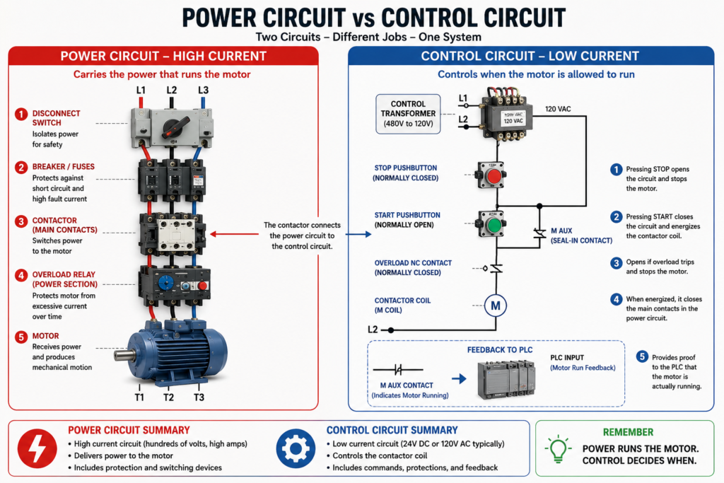
In industrial motor control, one of the first concepts every automation technician must understand is the difference between the power circuit and the control circuit.
Both circuits work together, but they do very different jobs.
The power circuit carries the current that actually runs the motor. The control circuit decides when that power should be applied or removed.
A simple way to remember it is:
The power circuit runs the motor. The control circuit decides when the motor is allowed to run.
This difference is extremely important when troubleshooting. A motor may fail to start because of a problem in the power circuit, the control circuit, the overload relay, the PLC output, the contactor coil, or even a field device such as a Stop pushbutton or safety interlock.
What Is the Power Circuit?
The power circuit is the high-current side of the motor control system. This is the part of the circuit that delivers electrical power to the motor.
In a typical three-phase motor starter, the power circuit includes:
- Incoming three-phase power: L1, L2, L3
- Disconnect switch
- Circuit breaker or fuses
- Contactor main contacts
- Overload relay power section
- Motor terminals: T1, T2, T3
- Motor windings
The motor control glossary defines the power circuit as the part of a relay or starter that actually provides power to the output component, such as a motor.
Basic Power Circuit Flow
A basic three-phase power circuit looks like this:
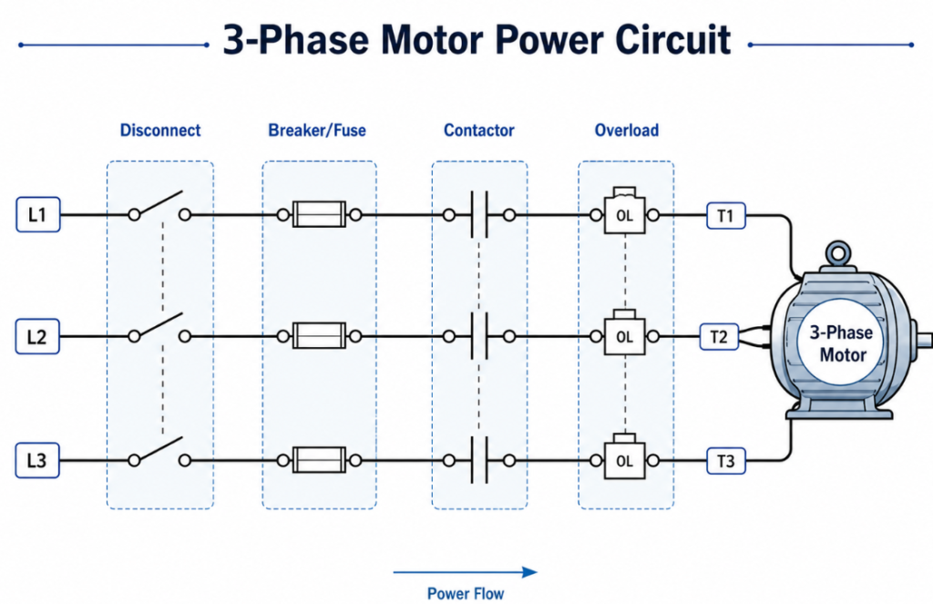
When the contactor is open, power does not reach the motor.
When the contactor closes, three-phase power is applied to the motor and the motor starts.
Main Components in the Power Circuit
1. Disconnect Switch
The disconnect switch provides a way to isolate power from the motor circuit.
Its purpose is to allow the circuit to be safely turned off for maintenance, troubleshooting, or equipment isolation. In real industrial work, the disconnect is also commonly part of the lockout/tagout process.
The motor control textbook emphasizes that lockout/tagout is used to remove the source of electrical power and prevent equipment from being energized while it is being worked on.
2. Circuit Breaker or Fuses
Circuit breakers and fuses protect the circuit against high fault current, such as short circuits or ground faults.
They are not the same as overload relays.
A breaker or fuse is designed to react to very high current. An overload relay is designed to protect the motor from drawing too much current over time.
| Device | Main Function |
|---|---|
| Circuit breaker / Fuse | Protects against short circuit and high fault current |
| Overload relay | Protects motor from excessive current over time |
| Contactor | Opens and closes motor power |
| Motor | Converts electrical energy into mechanical motion |
3. Contactor Main Contacts
The contactor is the electrically controlled switch that connects and disconnects motor power.
When the contactor coil is energized by the control circuit, the main contacts close. When the coil is de-energized, the main contacts open.
The glossary defines a contactor as an operating device that connects or disconnects the motor from the power supply through an electromagnetic coil and armature.
The main contacts are part of the power circuit because they carry motor current.
4. Overload Relay Power Section
The overload relay monitors motor current.
If the motor draws too much current for too long, the overload relay trips. This protects the motor from overheating and damage.
The glossary defines overload protection as a device or system that prevents an electric motor from drawing too much current, overheating, and burning out.
Important point:
The overload relay does not normally stop a short circuit. That is the job of the fuse or circuit breaker.
5. Motor Terminals
The output side of the starter usually feeds the motor through terminals identified as:
T1, T2, T3These connect to the motor leads. For a three-phase motor, reversing any two phases changes the direction of rotation. That topic will be covered later in the series when we discuss reversing starters.
What Is the Control Circuit?
The control circuit is the lower-current side of the motor control system. It controls the contactor coil, relays, pilot lights, PLC inputs, PLC outputs, and permissive logic.
The motor control glossary defines a control circuit as the circuit that controls a relay or contactor.
The control circuit usually includes:
- Control transformer
- Stop pushbutton
- Start pushbutton
- Overload auxiliary contact
- Contactor coil
- Auxiliary seal-in contact
- Pilot lights
- PLC inputs
- PLC outputs
- Safety contacts or permissives
- Relay logic
The control circuit may operate at 120 VAC, 24 VDC, or another control voltage depending on the machine design.
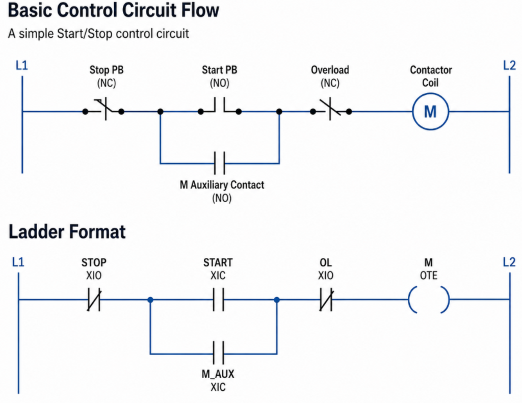
Basic operation:
- The Stop pushbutton is normally closed.
- The Start pushbutton is normally open.
- Pressing Start energizes the contactor coil.
- The contactor closes its main power contacts.
- The motor starts.
- The auxiliary contact seals in the circuit.
- Pressing Stop opens the control circuit.
- The contactor coil drops out.
- The motor stops.
Seal-in or memory logic as the action where pressing Start energizes the coil, closes the auxiliary contact, and creates a current path around the Start button until the Stop button breaks the circuit.
Power Circuit vs Control Circuit: Side-by-Side
| Feature | Power Circuit | Control Circuit |
|---|---|---|
| Main job | Supplies motor power | Controls when motor power is applied |
| Current level | High current | Low current |
| Typical voltage | 208 VAC, 240 VAC, 480 VAC, 575 VAC | 24 VDC, 120 VAC, or other control voltage |
| Main devices | Disconnect, breaker, contactor contacts, overload, motor | Pushbuttons, relay contacts, PLC I/O, contactor coil |
| Troubleshooting focus | Voltage, current, fuses, contacts, motor leads | Commands, permissives, coil voltage, PLC logic |
| Example labels | L1, L2, L3, T1, T2, T3 | Start PB, Stop PB, M coil, OL contact |
How the Two Circuits Work Together
A motor starter works because the control circuit controls the power circuit.
Here is the basic relationship:
Operator presses Start
        ↓
Control circuit energizes contactor coil
        ↓
Contactor main contacts close
        ↓
Power circuit sends voltage to motor
        ↓
Motor runs
Stopping the motor follows the opposite sequence:
Operator presses Stop
        ↓
Control circuit opens
        ↓
Contactor coil de-energizes
        ↓
Main contacts open
        ↓
Power circuit removes voltage from motor
        ↓
Motor stops
The control circuit does not carry the motor load current. It only controls the device that switches the motor load current.
Why Separate the Power and Control Circuits?
There are several reasons industrial systems separate power and control circuits.
1. Safety
A motor may run on 480 VAC, but the control circuit may use 120 VAC or 24 VDC. This allows pushbuttons, PLC inputs, and control devices to operate at a lower and more manageable voltage.
2. Troubleshooting
When power and control circuits are separated, troubleshooting becomes more organized.
You can ask:
- Is the control circuit commanding the motor?
- Is the contactor coil energizing?
- Are the main contacts closing?
- Is power reaching the motor?
- Is the motor drawing current?
3. Flexibility
The same motor starter can be controlled by:
- Local pushbuttons
- PLC output
- HMI command
- Float switch
- Pressure switch
- Relay logic
- HOA selector switch
4. Protection
The control circuit can include overload contacts, safety contacts, permissives, and interlocks before allowing the motor to start.
Important Concept: The Contactor Is the Bridge
The contactor is the bridge between the control circuit and the power circuit.
The coil belongs to the control circuit.
The main contacts belong to the power circuit.
Control Circuit Side:
Start PB → Stop PB → OL Contact → Contactor Coil

Power Circuit Side:
L1/L2/L3 → Main Contacts → Overload → Motor
When the coil energizes, the power contacts close.
This is one of the most important relationships in motor control.
Common Troubleshooting Example
Problem:
The operator presses Start, but the motor does not run.
Do not immediately assume the motor is bad.
Instead, separate the problem into two areas:
Check the Control Circuit
Ask:
- Is control voltage present?
- Is the Stop button closed?
- Is the Start button working?
- Is the overload auxiliary contact closed?
- Is the PLC output turning on?
- Is the contactor coil receiving voltage?
- Is the contactor pulling in?
Check the Power Circuit
Ask:
- Is the disconnect ON?
- Are the fuses good?
- Is the breaker tripped?
- Is voltage present on L1/L2/L3?
- Are the contactor main contacts closing?
- Is voltage present on T1/T2/T3?
- Is the overload power section passing voltage?
- Is the motor receiving three-phase power?
A strong troubleshooting mindset:
First prove the control circuit. Then prove the power circuit.
Example: Control Circuit Good, Power Circuit Bad
The contactor pulls in, but the motor does not run.
This tells you the control circuit is probably working because the coil is energizing.
Possible power circuit problems:
- Blown fuse
- Bad contactor main contact
- Tripped overload
- Loose wire
- Open motor lead
- Failed disconnect
- Motor winding problem
- Missing phase
Example: Power Circuit Available, Control Circuit Bad
There is three-phase power at the starter, but the contactor does not pull in.
Possible control circuit problems:
- No control voltage
- Stop button open
- E-Stop active
- Overload auxiliary contact open
- Bad Start pushbutton
- PLC output not turning on
- Broken wire to coil
- Failed contactor coil
This is why separating the two circuits mentally is so valuable.
PLC-Based Motor Control
In modern systems, the PLC often becomes part of the control circuit.
A typical PLC motor control system may include:
PLC Inputs
Start_PB
Stop_PB
Overload_OK
Motor_Run_Feedback
Safety_OK
Auto_Request
PLC Outputs
Motor_Starter_Coil
Motor_Run_Command
Pilot_Light_Run
Alarm_Light
Internal Logic
Motor_Start_Request
Motor_Run_Command
Motor_Failed_To_Start
Motor_Overload_Fault
The PLC does not replace the power circuit. It only provides logic to decide when the starter or VFD should be commanded.
Command vs Power
This is another critical point.
A PLC output may be ON, but that does not guarantee the motor is running.
There may be:
- Blown fuse
- Tripped overload
- Bad contactor
- VFD fault
- Bad motor
- Mechanical jam
- Missing phase
That is why motor feedback is important.
A professional control system should separate:
Command → Output → Power Device → Motor FeedbackExample:
Motor_Run_Command = PLC decision
Motor_Starter_Output = physical output to coil
Motor_Run_Feedback = proof from auxiliary contact or VFD status
Why Motor Feedback Matters
Motor feedback confirms that the motor actually responded to the command.
Feedback can come from:
- Contactor auxiliary contact
- VFD running status
- Motor current switch
- Encoder
- Proximity sensor
- Pressure/flow feedback from the process
Without feedback, the PLC may think the motor is running just because the output is ON.
That can be dangerous or misleading.
Example:
PLC Output ON
Contactor coil failed
Motor does not run
No feedback received
PLC generates Failed-To-Start fault
This is exactly the kind of logic that makes a motor control system more industrial and reliable.
Practical Field Example
Imagine a conveyor motor.
The operator presses Start on the HMI.
The PLC checks:
Safety_OK
EStop_OK
Overload_OK
No_Jam_Detected
Auto_Mode_Selected
Downstream_Ready
If all conditions are true, the PLC turns on:
Conveyor_Motor_CmdThat command energizes the motor starter coil or sends a run command to the VFD.
Then the PLC waits for feedback:
Conveyor_Run_FBIf feedback turns on, the conveyor is considered running.
If feedback does not turn on within a preset time, the PLC creates a fault:
Conveyor_Failed_To_Start_FaultThis is the industrial way of thinking:
Request → Permissives → Command → Output → Feedback → Fault DetectionTroubleshooting Mindset
When troubleshooting motor control, always ask:
Control Circuit Questions
- Do I have the command?
- Do I have control voltage?
- Are all permissives satisfied?
- Is the overload contact closed?
- Is the safety circuit healthy?
- Is the PLC output ON?
- Is the contactor coil energized?
Power Circuit Questions
- Do I have incoming voltage?
- Are all three phases present?
- Are the fuses good?
- Are the main contacts closing?
- Is voltage leaving the starter?
- Is the motor receiving voltage?
- Is the motor drawing current?
Feedback Questions
- Did the motor actually start?
- Did the auxiliary contact change state?
- Did the VFD report running?
- Did the process respond?
- Did current increase?
- Did the expected sensor change?
Common Mistake: Looking Only at the PLC
One common mistake in automation troubleshooting is looking only at the PLC logic.
The PLC may show that the output is ON, but the real-world power circuit may still have a problem.
Another common mistake is checking only the power circuit and ignoring the control permissives.
Good technicians troubleshoot both sides.
The PLC tells you what the system wants to do.
The power circuit proves whether the motor can actually do it.
Simple Technician Rule
Use this rule when troubleshooting:
If the contactor does not pull in, troubleshoot the control circuit.

If the contactor pulls in but the motor does not run, troubleshoot the power circuit.

If the motor runs but the PLC does not know it, troubleshoot the feedback circuit.
This simple rule can save a lot of time.
Final Thoughts
Understanding the difference between the power circuit and the control circuit is one of the most important foundations in industrial motor control.
The power circuit carries the energy that runs the motor. The control circuit decides when that energy should be applied. The contactor connects both worlds: its coil is controlled by the control circuit, and its main contacts switch the power circuit.
For automation technicians, this concept is essential for troubleshooting. When a motor does not start, do not guess. Separate the system into control, power, and feedback. Then prove each section step by step.
A motor control system is not just about making a motor run. It is about making the motor run safely, reliably, and with enough feedback to know what is actually happening in the machine.